TO MANAGE an engineering project well, you need the right tools. These tools include text processing, a CAD tool for system documentation, and spreadsheets or a small database to handle bills of material, wiring lists, and purchase order lists. The amount of data produced can create many files of differing types. Meanwhile, you need to ensure that all links and references remain accurate. If more than one person is working on a project the process becomes even more complicated. Keeping track of all this information can be cumbersome, to say the least. The newer generation of computer-based engineering tools makes life easier. All information is accessible through alphanumerical dialogs without the need to create or change diagrams. All steps starting with preliminary examinations, structuring of the facility, detailed electrical engineering including maintenance, modification and, finally, the deconstruction of the plant can be managed with an always-consistent virtual model. This approach is closer to the real work flow of electrical engineering: the primary engineering creates the project and defines the structure of a plant or machine and the main equipment. The device engineering follows to specify the main devices in detail, and to prepare the next engineering steps, as well as enabling early purchasing of devices. During detail engineering, electrical designers or experienced draftsmen create circuit diagrams, and decide details such as dimensioning of fuses, circuit breakers usage of terminals, wires, etc. Machine builders, system integrators, or engineering consultants might manage all these steps on their own. In larger companies this process could be spread over several departments or locations. To aid these efforts, Aucotec AG launched its Engineering Base (EB) electrical design software in Europe last year, and reports its scaleable product covers the entire project scope. Engineering Base now is available in the U.S. with an ANSI/JIC/IEC-compliant symbols library and sample projects. The built-in capability for automatic item labeling and wire numbering now accommodates U.S. needs, following rules related to the typical rung numbers.
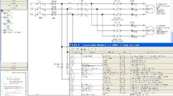
"THE BASIC concept of this software is to place all the information in one database where every object of the real plant, such as panels, devices and cables, is reflected in an appropriate database object, says Reinhard Knapp, Aucotecs product manager. These objects can be created, modified and deleted using convenient front-end components that present data in explorers, worksheets, edit dialogs or diagrams. Supplied with a preconfigured Microsoft SQL Server, EB software includes an easy-to-use administration tool, adds Knapp. The user interface has explorer-like hierarchical views and configurable table views in worksheet style. For 2-D diagramming, Microsoft Office Visio 2003 is included, and this immediately reflects every modification in the plant model. The most important benefit of Engineering Base is getting rid of the mess created by lots of CAD files and spreadsheets without any intelligent link, says Knapp. We replace them with a strong database where all information is kept in one place, while it shows up as graphical symbols on several documents. The opportunity to start your work wherever you need tomaybe without any graphics in the first placeis better than anything that specialized electrical CAD tools can provide. For example, if the designer is at an early state in the project, where only motor listings and field cable lists are to be produced, he just starts there with a bill of materials. Later on you can create detailed drawings guided by the information on motors and cables youve already produced, adds Knapp. When you show a core of a predefined cable on a drawing and connect it to a device, Engineering Base instantly will check if the details wiring matches the destinations of the cable. If you produce a panel layout drawing, you have access to the dimensions of the device and Engineering Base will provide scaled symbols. All you have to do is drag and drop them on the drawing. To meet the demands for the use of worldwide standards, the software has multiuser and multiple project capabilities for total coordination within an engineering workgroup, while the complete development and runtime environment of Visual Basic for Applications (VBA) is included. ANSI, JIC and IEC standards and libraries of compliant graphical symbols are part of the package, while other global standards are supported with complete shape libraries and additional features such as automatic item labelling and wire numbering.
For more information about Aucotec's Engineering Base (EB) electrical design software, call 630/485-5600, e-mail[email protected]or browse towww.engineeringbase.com.
| About this Product Exclusive |


