Peter Hammond recalls the birth of the medium-voltage drive


Hammond’s career coincides with the emergence of the power electronics market. This market was miniscule until several years after the thyristor or silicon-controlled rectifier (SCR) was invented in 1957 by GE, because the initial voltage and current ratings were too small. The thyristor followed a path similar to the transistor, which was invented in 1947, but did not mature enough for wide application for several years.
Hammond received his MSEE from Cleveland’s Case Institute of Technology in 1966, about the time the thyristor matured enough to build a drive that could handle 100 hp. After graduating, he worked for several small companies designing ac drives.

Peter Hammond,
father of the Perfect Harmony topology
“In 1977, I joined a company called Robicon, now part of Siemens," says Hammond. "Back then, we made ‘me-too,’ low-voltage drives, at 600 Vac or less, using thyristors. Our competitors were making similar drives. Everyone knew there was a big market if we could get beyond the low-voltage range into the medium-voltage range—4,160 Vac, for example—with power in the thousands, not the hundreds, of horsepower. We were looking for ways to scale up our existing low-voltage circuits, but there were lots of drawbacks."
One drawback: “If the semiconductors in a typical low-voltage circuit have the highest voltage ratings available, it’s still not possible to achieve 4,160 Vac,” says Hammond. "A second drawback is that, as you go up in horsepower, the power quality becomes more critical," he says. "Just scaling up the existing circuits doesn't give you any improvements in power quality."
Hammond was looking at ways to connect semiconductor devices in series for higher voltages, but that was very difficult, because the series devices needed to turn on and off at exactly the same moment. If one device turned off too soon, the other device would need to support the entire voltage and would fail.
Birth of the Perfect Harmony drive
Over a weekend in 1993 Hammond had an idea for a new approach for medium-voltage drives. "Mulling over the difficulty of connecting switching devices in series, it suddenly dawned on me that it would be easy to put complete converters in series, and that there would be many collateral benefits." says Hammond.
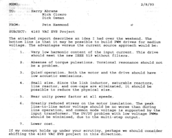
Figure 1: This first disclosure memo to managers at Robicon outlined the drive’s benefits, including efficiency, cost savings, unity power factor and reduced harmonics.
Source: Robicon/Siemens
His disclosure memo to managers outlined the benefits, including low harmonics, absence of torque pulsations, quiet operation, near unity power factor, and reduced stress on the motor (Figure 1). “These benefits would allow a medium-voltage drive to be installed without a special motor, without worrying about torsional resonance and without worrying about harmonic distortion. Management approved the project, and we had a prototype drive running in about a year."Hammond started working on the Perfect Harmony project with himself and one technician and later added a draftsman. "We were designing as we went along,” says Hammond. "The converters—we call them ‘cells’—were actually easy because once you decide to put a number of low-voltage converters in series to get the medium-voltage you need, the power required from each converter comes down. For example, if the number of converters, or cells, is 12, each cell only needs to supply one-twelfth of the power." With 12 cells, 1,000 hp can be produced with individual cells that are only rated at 84 hp (Figure 2).
"Not only were the circuits familiar from our low-voltage experience, but the devices were also familiar." says Hammond. "You don't need high-voltage devices if you are building low-voltage cells. You get the voltage you need by stringing cells in series like batteries in a flashlight. All the devices and the circuits we were using were old-hat to us."
The only thing new that Hammond's team had to deal with was connecting the cells in series with each other. "The cells needed to be electrically isolated", says Hammond. "That required three things. The physical structure supporting the cells had to be non-conducting, so fiberglass or other insulating materials were used. The power for each cell had to come from a dedicated and isolated winding of a transformer. And the command signals to the devices couldn't travel over wires; so we had to use fiberoptics. All these electrical isolation concepts were easily manageable."
[sidebar id=6]
The first customer was a university in Texas. The university ordered two drives for its campus air-conditioning system to operate chillers. Without a VFD, the chillers had to run at full speed, whether it was needed or not. The university saved money by slowing the chillers down on cool days, when the full capacity was not needed.
Quick growth
"Before we had even shipped the first order, an engineer from an oil company visited to witness the testing of an existing order for 20 low-voltage pulse-width-modulation (PWM) drives, to be installed on an oil platform in the ocean,” says Hammond. “These drives were going to operate submersible pumps located in wells drilled into the sea floor, a mile or more away from the platform. The customer understood that it wasn't feasible to transmit low-voltage power that distance, so he planned to step up the output from the low-voltage drives through transformers, before he sent it to the subsea pumps.”
Unfortunately the transformers also stepped up the harmonics and voltage steps from the drives. "If your wave form has steps in the voltage, each of those steps launches a traveling wave down the cables, and, when it reaches the subsea pump motor at the far end, the wave is reflected back, which doubles the voltage step." says Hammond. "With a step of several thousand Volts, you really stress the insulation in the motor, and, if the subsea motor fails, it is very expensive to retrieve and replace it."
"The customer’s engineer saw the prototype Harmony VFD, and canceled the low-voltage order, in spite of penalties. Instead he ordered 21 Perfect Harmonies, even though we had none running in the field." says Hammond (Figure 3). "That was our second order. Our sales group had estimated selling only two Harmony drives in the first year, but we ended up selling 47. We knew we had a hit at that point."
Although the ideal output voltage is a perfect sine wave, the Perfect Harmony comes close because it synthesizes the output voltage from many small steps, to be a good approximation to a sine wave, notes Hammond. "This was the feature the oil company liked best,” he says. “Additionally, the sources of power on oil platforms are diesel generators, with high impedance, so they don't tolerate harmonics well. The Perfect Harmony has very low harmonics on the input as well as on the output."
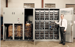
Figure 3: Peter Hammond, the father of the medium-voltage variable frequency drive stands next the first prototype unit.
Source: Robicon/Siemens
A third benefit the oil company didn't take advantage of was cell redundancy. "Because we divide the power circuit up into many identical cells, we can afford to lose one, and the drive will still operate, if we add a simple cell-bypass feature," says Hammond. "Although there is some minor degradation of the output voltage waveform, it is far better than not being able to run at all. The failed cell can then be replaced when convenient."Big blowers at utility generating plants take advantage of this benefit. These 5,000 hp blowers force air into the boilers, and draw out the exhaust gas to send it up the smoke stack. If one blower goes out, the whole power plant is down. The bypass option is always specified in such high-reliability applications. High-reliability requirements are another reason Perfect Harmony drives are also used for pipeline pumps and in petrochemical plants.
The path of least resistance
"The key event in my life that pointed me toward electrical engineering occurred when I was in eighth grade in 1954," says Hammond. "I lived on a farm and went to school in a small town. Local merchants had problems on Halloween, when their windows would get soaped or painted with graffiti. They decided to have a contest where students painted Halloween scenes on the windows, and I won. The prize was to go to the library and pick out one book. I picked a book called, A Boy and a Battery, which had a bunch of simple electrical experiments a boy could do. I think that first got me interested."
Hammond won a National Merit scholarship, so he was able to go to California Institute of Technology in Pasadena and received a BSEE in 1962. "I worked for a year and then went back to graduate school at the Case Institute of Technology in Cleveland, Ohio, where I received my MSEE in 1966. I then went into the power electronics industry and have stayed there ever since," says Hammond.
Hammond landed at Robicon in 1977, when they had just decided to get into the ac drive business. Robicon was a late comer to the market and chose to use a current-fed inverter design using SCRs. "I got in on the ground floor there, where my boss and I designed most of the drives in that low-voltage family. Soon after I joined Robicon, President Carter pushed legislation through Congress to fund municipal sewage upgrades all over the country. This created a large market for variable-speed drives. The joke was that we got started by pumping manure. These were low-voltage drives, but we learned a lot from the sewage lift station installations."
When it rains, it pours
“The motors and pumps in a sewage lift station must be sized for worst-case flow during a thunderstorm,” explains Hammond. "During normal conditions, the flow is significantly less, and if the motors and pumps continue to run at full speed they are very inefficient. With variable-speed drives the speed can be optimized for the actual flow, saving a lot of energy.”
[pullquote]
The sewage lift stations are distributed throughout the neighborhoods they serve, so that they receive power from the same utility grid as the residents. “The early low-voltage drives drew significant harmonic currents from the grid, causing harmonic voltage distortion,” explains Hammond. “Residential neighbors were complaining about their TVs flickering and a humming noise on the telephones."
To reduce these problems, Robicon tested phase-shifting between drives, using small transformers. This cancelled some of the harmonic currents and reduced the distortion. "This was the first piece of the puzzle that we later put into Perfect Harmony—canceling harmonics by phase-shifting," says Hammond.
Another drawback of the early drives was that, when the motor speed was reduced, the power factor on the input decreased. "The drive drew more current than was needed, because some of the current was reactive—current was flowing that didn't do useful work because it was out of phase with the voltage," says Hammond. "Utilities have penalties for poor power factor, so Robicon developed filters that both reduced harmonic distortion and corrected the power factor."
In the beginning, there were so few variable speed drives in operation that the harmonic issue wasn't critical, notes Hammond. There were very few complaints. However, as more and more drives were installed, it became important. The IEEE issued Standard 519 to limit the harmonic distortion allowed. By the mid-1980s, almost every drive order required minimizing harmonics and power factor correction.
“The ac drive sales at Robicon went from zero in 1977 to about $20 million in 1993,” says Hammond. “Then, when the Perfect Harmony came along, sales just exploded. By 1997 we were pushing $200 million in sales.”
The path to Perfect Harmony
A simple description of a Harmony drive would be a group of cells with rectifiers that take three-phase ac voltage from a special transformer and convert it to dc voltage. The dc voltage is then converted within the cell back to ac voltage at a different frequency, using a PWM inverter. The inverter is a little more complicated than the rectifier because the output switches need to be controllable—in this case, using insulated gate bipolar transistors (IGBTs). The cells in Perfect Harmony contain the rectifier, a bank of capacitors to filter the dc and the inverter devices.
In a Harmony drive, the number of cells is always a multiple of three, to generate the three-phase output voltage. The number of cells per phase depends on the required maximum output voltage. Because the cells contain capacitor banks, they don't need to switch simultaneously. Switching these cells at slightly different times reduces the step size in the output voltage and increases the number of steps. By controlling the timing of many small steps, instead of a few large steps, the output voltage can become a good approximation of a sine-wave.
Later years
"Our early experience was all low-voltage," says Hammond. "We had a lot of learning to do when we got into the medium-voltage market. Fortunately, we erred on the side of caution. The first drives were built like tanks but were expensive and bulky. As time went on, the enclosure was trimmed down a bit, but still got the job done. Now we are at the third or fourth generation of drives."
In 2005, Robicon was acquired by Siemens. The only product Siemens wanted was the Perfect Harmony. All other products were sold off. Hammond retired at about the same time but continues to work part-time as a senior consulting engineer for Siemens.
"When the Perfect Harmony first appeared, our expectation was that a new product would only last 10 years and that we needed to start working on a replacement immediately." says Hammond. "But, so far, 20 years down the road, the Perfect Harmony is still competitive, and it's still the same circuit. The topology still has a lot of life left in it, and it's still made in Pittsburgh, Pennsylvania. Sooner or later, there will be a new medium-voltage drive design or concept that will beat out the Perfect Harmony. We just haven't seen it yet.”
To highlight the need for arc flash protection, start by considering most voltage levels above 30 V as dangerous, but at medium-voltage levels (600 V to 69 kV), the danger present increases and so does the plasma arc's energy. For example, with a plasma arc, the breaking point is 600 V between low voltage and medium voltage. Below 600 V, if an arc does start, it often goes out by itself, as the alternating voltage goes to zero, the arc stops unless perhaps it is an arc welder. Above 600 V, that doesn't happen. Now you have the potential for a meltdown, sometimes an explosive one. This adds requirements to the medium-voltage world such as arc-proof enclosures.
When the arc occurs, it’s almost like an explosion, as an enormous amount of power is being pumped into the arc. This is a potential problem with all medium-voltage applications. The gas or plasma must be vented to keep the cabinet from rupturing. This requires rupture disks and possibly duct work to route the plasma to a safe area. Another issue is radiation. There is so much power concentrated in the area where the arc occurs that significant radiant heat and ultraviolet light is emitted causing a full body sunburn in a split second. Flash-proof suits and helmets are required. Wear arch flash protection equipment with the proper ratings as it may just keep you from reaching vaporizing temperatures during an arc flash incident.
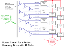
Figure 2: A special transformer and multiple cells in series is basis for the Perfect Harmony medium-voltage variable frequency drive.
Source: Peter Hammond
About the Author

Dave Perkon
Technical Editor
Dave Perkon is contributing editor for Control Design. He has engineered and managed automation projects for Fortune 500 companies in the medical, automotive, semiconductor, defense and solar industries.
