Machine safety includes pneumatics
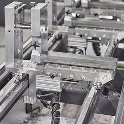
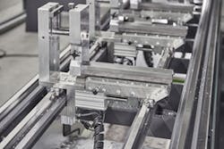
Figure 1: Add a 2-inch cylinder and some tooling edges, and it is clear that pneumatic safety must be included on machines.
(Source: Aventics)
Both operator safety and machine safety are at the front of the line during design and development. A safe integrated design starts during the sales and concept phase and may be the first and last item during site acceptance testing.A wide array of safety components—from the guard door sensors and light curtains on the machine to the safety relays, safety controllers and safety PLC in the control cabinet—is available to ensure the machine design meets industry safety standards.
An integrated safety and control system can take many forms while protecting the operator and machines from injury or damage, but there can be problems when integrating machine safety and control. Some may even say it gets in the way.
There are some best practices to use when developing these machine safety systems. While safe control of electrical power using the appropriate hardware or safety PLC gets all the attention, it’s equally important to take a look at some of the safety practices for the control of fluid power (Figure 1). It's good to dump all the air under an emergency-stop situation, but sometimes it's OK to maintain air pressure as, long as it doesn't cause a safety hazard.
Safety is getting in the way
"We are always working to achieve the correct balance between providing a safe tool that meets industry standards and one that’s not so restrictive that the end user finds the tool difficult to use," says Doug Putnam-Pite, director of software development at Owens Design (www.owensdesign.com) in Fremont, California. "If a tool is overly restrictive, then the end user will override safety devices for day-to-day tasks, leading to an unsafe operating environment. To achieve the correct balance requires a multi-discipline approach to tool safety and usability. Mechanical, electrical and software groups must work together with the end customer to come up with a safe and usable tool design."
The most challenging aspect of integrating machine safety and control isn’t so much the integration, but properly handling all types of stops and restarts, notes Leon Krzmarzick, controls engineering manager at Delta Technology (deltatechinc.com) in Phoenix, Arizona. "There are many affordable safety solutions available today that are both flexible and easy to maintain," he says. "However, safely turning off power and dumping system air can cause all types of machine control issues that must be simulated and tested to ensure proper system recovery. Parts can be dropped, tooling can drop due to gravity or crash on startup, and there are many other scenarios. The tooling and pneumatic systems must be properly designed and the program must be written to restart the machine by returning to a home or known position safely, as well, and resuming automatic cycle with minimal operator intervention."
Some safety best practices
"The best approach is to try to design any hazard out of the system in the first place," says Delta’s Krzmarzick. "If a hazard cannot be eliminated, try to reduce the likelihood and severity of the injury. If the risk is minimal, a simpler safety control system may suffice, but it is important to understand the safety requirements and to provide a safety system that is easy to troubleshoot."
Control safety implementation has evolved in an interesting way in recent years, continues Krzmarzick. "In the past, we would often design a Category 3 or 4 safety circuit using a simple safety controller, even if a Category 2 circuit may have sufficed. The mentality was: better safe than sorry," he says. "The downside to these circuits is their complexity. These circuits can be difficult to troubleshoot, and the likelihood of someone defeating the safety system increases with complexity. Older systems may have had daisy-chained interlocks with no indicators on each device, which can be especially difficult to debug in a dual-chain circuit. Magnetic-coded safety switches can compound these issues."
Today, there are many options that can make safety circuits much easier to troubleshoot. "Programmable safety controllers are now very affordable, and they provide many benefits," says Krzmarzick. "First, they can handle a large number of inputs, meaning that every safety device can be wired directly to the controller, eliminating the need to daisy-chain devices. Second, the controllers can be networked with the tool’s PLC, allowing status information for every device to be displayed on the HMI. Third, the controllers are flexible and can be programmed as needed to handle multiple zones and time delays. Controllers are even available with built-in displays that show the status of each device."
Safety networks are also available, eliminating the need to wire each device back to the controller, while still providing status information for each device. "This can greatly reduce wiring in large applications without the drawbacks of the old daisy chains," says Krzmarzick. "The ability to see the status of each device is a huge advantage. In the past, a third contact would often be used to monitor a device. However, this approach is of no help if a contact is bad or there is failed wire in a daisy-chained safety circuit."
Owens Design follows NFPA 79, when designing the electrical systems for tools says Putnam-Pite. "Wherever possible we try to use electrical components that are UL-certified,” he notes. “All our tools have emergency off (EMO) buttons and related safety circuitry. Generally, all tool doors and panels are either locking or require a tool for removal."
What customers should know
"Safety is really a question of liability," says Delta's Krzmarzick. "If someone gets injured, how exposed will the employer be? Was a proper safety assessment completed? Were steps taken to mitigate risks to personnel? There is always a risk of a lawsuit, but with no safety planning, the employer has little ground to stand on. Proper safety implementation has become much more affordable in recent years, and there is no excuse for cutting corners."
There are many regulations that need to be met when installing automation equipment, says Putnam-Pite. "The machine often must meet local and state regulations before the equipment can be powered on," he explains. "Additionally, many industries have their own safety standards that must be met. If the tool is not properly designed to meet these standards, the equipment commissioning will be delayed and costly field upgrades may be required."
Dump the air?
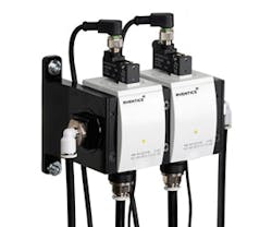
Figure 2: Just like redundant electrical contactors for safety, these redundant pneumatic valves with monitored spool positions or pressures meet Category 3 safety requirements.
(Source: Aventics)
"Tool pneumatics often contain stored energy," says Owens’ Putnam-Pite. "These sub-systems are potentially dangerous to tool users. The energy stored in these pneumatic systems must be removed during an emergency stop."The release of pressure reduces the potential energy in the system, says Erl Campbell, key account manager at Aventics (www.aventics.com). "The designer needs to look at each actuator in the system and determine the required control of movement in an emergency," he says. "One actuator may just need to be exhausted, while another may need to be stopped by other means. The actuator can be stopped mechanically or by trapping air on both sides of the piston using a three-position valve or pressure-operated check valves. Lastly, an actuator can be returned to a safe position, either extended or retracted, using a spring return valve."
A safe exhaust is probably the most common pneumatic circuit used for machine safety. "The circuit is used to exhaust air from the machine or cylinder preventing trapped potential energy," says Campbell. "Machine builders typically find that a Category 3, which can cover a performance level of a-d is required. The function can be accomplished with an integrated device or by design using standard off-the-shelf pneumatic components optimized for the machine or application. The designer will use two three-way valves in series to exhaust the system, and the valves can be monitored with sensors that detect spool or valve position or indirectly via flow or pressure sensors, depending on the PL required (Figure 2)."
Safely pressurized
"Often tooling that holds parts should remain safe for the held part during an emergency stop," says Owens’ Putnam-Pite. "A robot and pick-and-place end effector are examples of subsystems where the device shouldn't open and drop parts during an emergency stop. Pneumatic end effectors can be designed to be normally closed. When air is dumped during an emergency stop, the gripper remains closed and the operator is safe from stored pneumatic energy."
Aventic's Campbell notes that pneumatic systems vary greatly from one application to another. "Engineers and designers need to evaluate the system to determine what should happen in an e-stop situation," he says. "One pneumatic system may be supplying air pressure for a vacuum application, which, in an emergency stop, could lose vacuum and drop items being held. Some cylinder applications may be controlled mechanically by means of a rod brake. The rod brake will prevent movement of the actuator, regardless of the air in the system."
Trapped air hazards
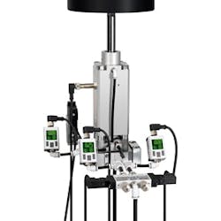
Figure 3: In applications where it is necessary to hold a cylinder's position after an emergency stop, a rod lock, with diagnostic sensor, can be used instead of using trapped air.
(Source: Aventics)
"The tool needs to be designed from the start with the goal of not having trapped air during an emergency stop," suggests Owens Design's Putnam-Pite. "Design reviews can find areas of the tool that may not have been designed correctly and the deficiencies corrected before the tool is built. Design verification testing (DVT) after the tool build can also eliminate any unsafe conditions for the tool user."Safe holding and protection against unexpected startup circuits can be used to hold a load and ensure it does not move, says Campbell. "The use of pressure-operated check valves on cylinder ports can prevent air movement in a cylinder," he says. "The trapped pressure will prevent the cylinder from moving. Diagnostic coverage could be obtained from a pressure switch in the circuit. Another solution would be to use a rod lock, which is typically a pneumatic device installed on the piston rod of the cylinder. The lock will only allow the cylinder to move when air pressure is sent to the port on the lock. Some manufacturers have a sensor to directly detect that the rod lock is engaged for increased diagnostic coverage (Figure 3)."
Risk assessment
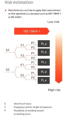
Figure 4: A risk assessment, developed within ISO 13849, outlines the process by which machine builders determine safety requirements by considering severity, frequency and avoiding a hazard.
(Source: Aventics)
"The design of safe pneumatic circuits begins with a careful risk assessment," says Aventics’ Campbell. "The process involves designers of all systems within a machine and/or process from mechanical to electrical. The first step is to look at the project and identify any potential hazards and risks for injury. The next step is to do a risk estimate and evaluation of each hazard. The engineers or designers can then develop the appropriate preventive measures to minimize the risk to acceptable levels. The standard developed within ISO (ISO 13849) outlines the process by which machine builders can develop their own standard for meeting the guidelines with the goal of making machines as safe as possible (Figure 4). The standard addresses the control of a machine and not the actual moving components—cylinders, actuators. Pneumatic circuits are usually only one part of a machine that could pose potential hazards."The risk assessment of pneumatic circuits examines each actuator and its movement to determine if potential hazards, such as pinch points, exist. "The hazards may already be addressed in the original machine design, as guarding or other obstacles may already be present," says Campbell. "The easiest way to avoid the hazard would be to prevent access to the area; however, the machine function and/or application may require access either when running the machine or in a maintenance mode. The design team works together to identify all areas where more control is required. The ISO standard focuses on the control aspect of the circuit. However, at this point it would also be a good practice to ensure that the actuators used have been properly sized for the application.”
ALSO READ: The popularity of integrated control and safety continues to improve
Be safe
There are many pieces to integrated safety and control on a machine, and the safety shouldn't get in the way. Following some best practices, as well as working closely with the end user to develop, test and understand the safety system, is a must.
The application of pneumatics and its integration into the safety and control system adds another layer of requirements, development and testing. Air is an energy source that must be safely controlled, much like electricity. Whether it’s a zoned safety application or controlling a single cylinder that causes a pinch hazard, the energy must be safely removed or trapped without causing additional hazards.
[sidebar id=6]

About the Author

Dave Perkon
Technical Editor
Dave Perkon is contributing editor for Control Design. He has engineered and managed automation projects for Fortune 500 companies in the medical, automotive, semiconductor, defense and solar industries.
