A Control Design reader writes: What are some of the key steps controls engineers should consider for main electrical enclosure design? Any recommendations on spare-space percentages in a junction box or main electrical enclosure? Is 20% a hard rule? What about key code areas in NEC and NFPA 79 to be aware of?
Answers
Final installation location and application
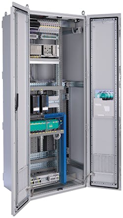
When it comes to main or any electrical enclosure design, a key step that surpasses all others is fully understanding the application and final location of use or installation (Figure 1). Based on this, it can be determined if there are standards that are good to follow or must be followed along with a product certification in order for the panel to be used and installed. Failure to understand all required standards and installation requirements will lead to a design that is at best not optimized, and in a worst-case scenario cannot be used. When it comes to specifics, it is best to consult with internal product compliance specialists within your company to determine which standards are applicable to the type of equipment being designed. If an internal expert is not available, seeking an external consultant that has knowledge of the requirements for your specific type of equipment can fulfill this requirement and get your design project started in the right direction.
Figure 1: Most important for determining the required standards is the enclosure’s final location and application.
From a generic, high-level standpoint, the final installation requirements are generally dictated by the National Electrical Code (NEC) or the National Fire Protection Agency (NFPA) 70 standard in the United States. This document will specify a number of items when it comes to installation requirements such as wire size, permitted equipment, spacings based on voltage and a number of other considerations for a proper and safe installation in a variety of settings and functions. When designing an industrial control panel or any electrical panel, it is important to assure that it can be installed properly, so consultation to the NEC is a general good starting point for quality panel design.
For a general consideration of an electrical or industrial control panel design, in addition to the considerations for proper installation, there are a number of product safety standards that could be consulted, especially if the design is to be listed or certified by a nationally recognized testing laboratory (NRTL). A good place to start is the scope of UL 508A. This is a generic industrial control panel design standard. The scope of this document lists various types of other panels that UL 508A would not cover. For example, portable control panels are covered by UL 1640, and termination boxes are covered by UL 1773. By reviewing the scope, you can determine if UL 508A would apply or if there is another, more specific standard that should be followed.
Additionally, if the panel is specific for machinery control, standards such as the ANSI B11 series, NFPA 79 or a number of Occupational Safety and Health Administration (OSHA) requirements found in OSHA 29 CFR 1910 and CFR 1926 may also be applicable.
Finally, if the panel is involved with an installation that is tied to a hazardous or classified location that would fall within the installation requirements of Articles 500-506 in the NEC, these panels will need additional consideration and protection for use in these hazardous areas. Depending on the area of classification and the protection concept being used, standards such as UL 698A, UL 121201, UL 1203, UL 913 or those in the UL 60079 series will also need to be met.
Ryan Brownlee / global compliance and technology consultant / Pepperl+Fuchs / www.pepperl-fuchs.com/usa/en
Future expansion needs
At all points, designers need to consider not only the current scope of work from the customer and environmental and rating requirements, but also future expansion needs. So, 20% spare space is a good rule of thumb, but could be different depending on the type of application and customer.
One other thing to consider is the ongoing advances of machine connectivity and the Industrial Internet of Things (IIoT). Manufacturers may look to add new technologies to their equipment, and, while many of these are software-based, there is often the need to add in hardware to the control panel.
Key steps to consider for main electrical enclosure design:
- component selection
- enclosure type and size
- component layout
- safety and regulations.
Key code areas in NEC and NFPA 79:
- general operating conditions
- protection from electric shock
- protection of equipment
- grounding
- conductors and cables
- wiring practices
- marking and safety signs
- testing and verification.
Rob Brodecki / service product manager / Mitsubishi Electric Automation / www.mitsubishielectric.com
Key knowledge areas
Control panel design requires knowledge in many key areas, such as codes. Hazardous-area considerations may define the type of protection required of the enclosure and/or the components mounted internally and/or HMI components mounted externally.
If you need to show evidence of a third-party certification to the municipal inspection authority and to the purchaser of the panel, the pertinent standards of that certification agency must be followed. For example, if the panel must be UL-approved, the pertinent UL standards must be followed. This may dictate the components that may be allowed.
The UL508A standard is the standard most of the municipal inspection authorities look for when cabinet designs are inspected. A panel ship can self-certify the cabinet design to UL 508A, if qualified. It must pass a test by UL to confirm knowledge of UL 508A.
For electrical considerations, follow the applicable codes (NFPA handbook) and UL standard when required for wire size, type and color or insulation, and fuses and circuit breakers.
Various methods for controlling the internal temperature can be utilized if necessary: selection of the exterior color, insulation, air purging, insulation, heater/thermostat, compressed air cooler, air conditioning, isolated thermal transfer with heatsink, sun shield and cabinet size. Thermal considerations include:
- the temperature rating of the items in the enclosure
- the heat output of those items
- the ambient conditions where the assembly will be installed.
Also read: Which panel design standards are relevant?
Designers should have familiarity of various components. This comes with experience and involves knowing what types of components are acceptable for the sector you are selling to. Having knowledgeable vendors and distributors can be a big help. Important components include:
- enclosure
- wire ducts or guides
- wire markers
- terminal blocks
- fuses, circuit breakers
- HMI components.
Client’s requirements can be identified with questions such as:
- Where it will be located?
- How will the client access it?
- Does it need a convenience outlet or internal lighting?
- From what direction(s) will the client run cabling or conduit?
- What are the wire, terminal and component labeling requirements?
Other space considerations, if not defined elsewhere, include:
- space needed between components
- space between component wiring terminals and wire ducts
- size of wire duct
- space to allow between cable entry and ducts or components
- space around the edge of the panel
- location of some components relative to others for ease of access, consideration for inter-wiring, grouping of signal types or other factors
- spare space recommendation of 15% to 25% for potential future device additions.
Michael Corwin / manager, customer support / Moore Industries / www.miinet.com
eHandbook: A practical guide to electrical enclosures
Design maturity
Key steps for electrical enclosure design include the following:
- Use appropriate enclosure type rating for the environment it is located in, such as indoor, outdoor, corrosive, wet, dust, dirt and submersion in water.
- Type 1 enclosures can be fabricated following UL 508A guidelines; other enclosure types are usually purchased and have an appropriate type rating. Alternatively, enclosures can be fabricated and tested for a particular type rating.
- Determine how the enclosure is to be mounted: wall, floor or pole.
- Heat calculation should be run to determine if the enclosure can dissipate the heat generated and not exceed the temperature rating of the components inside. Enclosure size can be increased if necessary, or climate control equipment may need to be added.
- Consult installation instructions of any component that generates heat. These instructions will define any required clearances to adjacent components which can affect enclosure size.
Recommendations on spare space percentages include these:
- In the case of industrial control cabinets, this is totally up to the designer/customer and depends on the likelihood of adding equipment to the cabinet in the future. Is the plant, machine or process design mature? The heat calculation should be considered. If the temperature of the cabinet is close to the maximum, consider not adding any spare space to prevent the addition of components that might add heat and exceed the maximum temperature.
- In the case of junction boxes, consult NEC, article 314.
Key code areas in NEC or NFPA 79 include:
- enough space for conductors
- room for bend radius for larger conductors
- room for any conductors running through enclosures
- room for part replacement and without being crowded
- touch safety, if any exposed electrical parts are greater than 50 Vac/60 Vdc
- NFPA 79 requirement of a print pocket.
Jim Gehenio / engineering manager, industry management & automation—automation solutions R&D/ Phoenix Contact / www.phoenixcontact.com
Boundary conditions, safety and function
In the main control panel, there are a lot of important issues to be considered, and all of them are relevant. If we must consider a sequence of points to be addressed, I would start by the boundary conditions that must be accomplished and are out of the control of the designer, followed by the safety aspects of the panel functional aspects—all of them extensively described in NFPA 79—and finally would consider the marking, tests and documentation of the panel.
Starting by the boundary conditions, normally they include the following:
- Maximum dimensions of the panel: limited by the available space where it will be placed and by the access to this place. Remember that the available room for the panel is probably the first question to be considered before starting any other action just because normally it is not under the control of the panel designer, it will affect all the other steps, and it has actually the potential of making the design unfeasible.
- Mains supply voltage—three-phases, single phase or dc—will affect all selection of the protection circuits in the input of the panel and the disconnecting means of this panel. This topic is described in NFPA 79: 2021, chapters 5 to 7.
- The external environmental conditions and temperature are also important because those will define the protection type of the panel and the correct strategy of cooling and/or heating of this panel. The protection types are defined in NFPA79:2021, Chapter 11 with additional information in Annex F.
Discussing the safety aspects of the panel include these:
- Overcurrent protection, internal access to the panel, insulation of live parts, and all procedures related grounding and bonding of the panel are deeply discussed in NFPA 79: 2021, chapters 6 to 8 .
- It is also important a clear evaluation of the wiring, considering the temperature inside the panel and the limits defined by different loads, such as motor loads, different voltages on the cables, which must be separated, and the function of each cable—grounding, mains, control voltage. These aspects are discussed in NFPA 79: 2021, chapters 12 and 13.
- Finally the safety systems responsible for disconnection of the panel as a normal operation or in case of failure must receive special attention. They are described in NFPA 79:2021 79, chapters 5 and 7.
Regarding functional aspects, here we have the most of subjective points due the fact that most of them are more related to best practices in terms of assembly and operation of the panel:
- Spare space: It is always recommended to offer a minimum of 10%, reaching 30% if we can foresee an increasing of functionality of the panel for future updates. Regarding this point we always must consider that we already have solutions that allow the expansion of control points in a control panel without increase the footprint of the components.
- Temperature calculation: We have tools to give us the calculation of maximum reachable temperature inside the panel considering the power loss of the components, external temperature and panel size. We only must consider that, if there is spare space in this panel, the components that will fill this space in the future also can have some power loss; therefore, in the same way that we consider space spare, we also should consider spare power in our cooling system to keep the temperature of the panel at specified despite the inclusion of new devices.
- Power supplies selection: Most control panels need a stable control voltage that is supplied by a good quality power supply. One popular orientation is to not use more than 80% of the nominal current of the power supply. On one hand, it is valid considering future expansions and also considering that fluctuation in the load is common and can be supplied by this extra current; on the other hand, it is less relevant if the selected power supply already has a long-term power reserve that allows the power supply to work with spare also in nominal conditions. For wiring separation, the NFPA 79: 2021, Chapter 12, discusses the separation of wiring with different voltages, but there are other aspects also to be considered in terms of wiring routes inside the panel.
Testing, verification, marking and documentation include the following:
- The tests to confirm galvanic insulation of the panel and the tests to confirm the functionality and selectivity of the overcurrent protection and ground-fault circuit interruptor (GFCI) are basic parts of the process.
- Finally, the designer must consider that these panels, during their lifetime, will receive interventions of maintenance, which will only be possible with clear documentation and clear markings. The NFPA 79: 2021,Chapter 17, explains clearly the aspect-related documentation. The same standard in Chapter 16 presents the demand of marking, focusing in the signalization-related safety. It is important but certainly is not enough. Despite the quality of the documentation, the maintenance efforts will increase a lot if there is a lack of identification in the panel of each connection point, each wire and each device. Therefore, a good recommendation for a high-quality panel, despite all points above mentioned is to specify and use all the marking possible, for each device, each connection point and each end of cable, imagining that the markings will be used during the lifetime of this panel and must be visible during this time.
Reinaldo Cozzo / division head manager, APS / Weidmüller / www.weidmuller.com
