A Control Design reader writes: What is the standard method of using circuits for e-stop conditions and their categories? Are there cases in which an e-stop button can be software-based?
ANSWERS
Safety and risk assessment
From a machine designer perspective, the safety system that is being designed into the machine and the risk assessment for the machine will determine which components are needed in the safety system. E-stop switches are just one of the components of the safety system. There are many industry standards that need to be followed to accomplish this, below are a few examples:
- DIN ISO 13849-1, Safety of Machinery
- DIN ISO 13850, Safety of machinery—Emergency stop function—Principles for design
- IEC 60947-5-1, Low-voltage switchgear and control gear
- EN 60947-5-5, Control circuit devices.
In my experience, an e-stop has to be a physical switch versus an icon or software-based to meet the above specifications and industry standards (Figure 1).
JOE TORZILLO / vice president sales, HMI components / EAO / www.eao.com

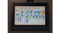
Figure 2: Possibilities exist by utilizing software-based safety, in this case, STO safety subfunction. (Source: Mitsubishi Electric)
Safe torque off
I’m not sure if there’s a standard method of using circuits for e-stop conditions; however, there are a number of ways to configure an e-stop button in a servo drive system. Here is one example: the image in Figure 2 illustrates what’s possible by utilizing software-based safety, in this case, STO safety subfunction.
E-stop buttons can be used in a number of configurations, but in their simplest form, they cut power to drive components when pressed to prevent damage to machine components or to prevent operator injury. In a hardware-based solution, power is cut to drive components via a series of magnetic contactors when the e-stop button is pressed. This serves the purpose of an e-stop by allowing motion to come to an uncontrolled stop, but the downside is that cutting power to the drives requires the drive to fully start up when the e-stop condition is removed.
In a software-based solution, the system configuration uses software-based safety subfunctions, in this case safe torque off (STO). Safe torque off cuts torque producing current to the servo motor when the e-stop button is pressed bringing motion again to an uncontrolled stop. The benefits of using safety sub-functions such as STO is that the magnetic contactors are no longer required, which reduces system costs and the power to the drive is not cut, which reduces start-up time.
We have a full range of safety subfunctions, in addition to STO, offered with safety over network that allow for more advanced safety features. Table 1 includes a full list of the range of offerings, including a brief definition for each.
DAN ZACHACKI / senior product marketing engineer / Mitsubishi Electric Automation / us.mitsubishielectric.com/fa/en/

Safe torque off (STO)
Responding to the input signal from external equipment, the STO function shuts off power to the servo motor electronically using the internal circuit (shuts off through secondary-side output). This function corresponds to the Stop category 0 of IEC/EN 60204-1.

Safe operating stop (SOS)
This function monitors the position of the servo motor not to deviate from the specified range. Power is still supplied to the servo motor during the SOS function.

Safe direction (SDI)
This function monitors whether the servo motor moves in the command direction. If the servo motor moves in a different direction from the command direction, the STO function is executed.

Safe stop 1 (SS1)
Responding to the input signal from external equipment, the servo motor starts to decelerate. After the set delay time for the motor stop is passed, the STO function starts. Monitoring the servo motor deceleration based on the motor deceleration rate is also supported. This function corresponds to the Stop category 1 of IEC/EN 60204-1.

Safe brake control (SBC)
The SBC signals are outputted for external brake control.

Safely limited increment (SLI)
This function monitors the travel distance of the servo motor not to deviate from the specified range. If the travel distance exceeds the range, the STO function is executed.

Safe stop 2 (SS2)
Responding to the input signal from external equipment, the servo motor starts to decelerate. After the set delay time for the motor stop is passed, the SOS function starts. Monitoring the servo motor deceleration based on the motor deceleration rate is also supported. This function corresponds to the Stop category 2 of IEC/EN 60204-1.

Safely limited speed (SLS)
This function monitors the speed of the servo motor not to exceed the specified speed limit. If the speed exceeds the limit, the motor power is shut off by the STO.

Safe speed monitor (SSM)
The SSM signals are outputted when the speed of the servo motor is below the specified speed limit.

Safely limited torque (SLT)
This function monitors the torque (or the thrust) of the servo motor not to deviate from the specified range. If the torque (or the thrust) exceeds the range, the STO function is executed.
Table 1: A full range of safety subfunctions, in addition to STO, are offered with safety over network that allow for more advanced safety features. (Source: Mitsubishi Electric)
Emergency stop vs. stop categories
The idea that the terms “e-stop,” “emergency-stop” and “stop categories” are equivalents is a common misconception. An emergency-stop function, which is normally linked to an emergency-stop pushbutton, or e-stop, in a machine, refers to a safety function that must be initiated by a single human action and is intended to minimize hazards to people, as well as damage to machinery or works in progress. Since this safety function does not prevent people from being exposed, it is considered a complementary protective measure, according to ISO 12100:2010 and ISO 13850:2015.
Stop categories, on the other hand, refer to the way in which a machine will stop. These categories, which are based on IEC 60204-1 and NFPA 79, can be defined as follows:
- Category 0 is a means of stopping the machine through the immediate removal of power to its actuators and is considered an uncontrolled stop. An example of Category 0 is to pull a plug and wait until the machine has completely stopped.
- Category 1 is a controlled stop with power to the machine actuators available to achieve the stop condition. This category allows powered brakes, so the power has to be available until the machine stops. For example, in a machine that uses drives, the stop is generated with a controlled deceleration ramp before disabling the drive’s output to the motor. In this case, the drive works as an actuator to bring the motor into a non-torque state after the deceleration. Once the machine motion has ceased completely, the power will be removed.
- Category 2 is a controlled stop with power left available to the machine actuators. An example of this category is a normal production stop in which the machine is brought to a stop and power is available to start at any point.
According to IEC 60204-1, an emergency stop must operate as either a Category 0 or Category 1 stop as determined by a risk assessment. Both of these categories require that the emergency stop function override all other operations and functions, so a restart is possible only after a manual reset. Category 2 is not suitable for an emergency stop function because power is still available after the machine stops, and no additional measures are required to restart the machine.
Also read: How to improve the safety of an operating machine beyond just an e-stop button
To provide an example of an emergency-stop function that performs a Category 0 stop, we can consider a safety circuit in which an emergency stop pushbutton (e-stop) is identified as S1, a reset button as S2, a motor as M, and contactors as KM1 and KM2 (Figure 3). All of these devices are connected to a status-monitoring relay, which ensures the switching action and provides contactor monitoring through T31 and T32. When the e-stop is activated, it will cause the contactors to isolate the power from M. The power to M is kept removed until e-stop S1 is released and reset switch S2 is pressed.

Figure 3: An emergency-stop function can perform as a Category 0 stop. (Source: Omron Automation Americas)
This will exemplify a scenario where an emergency stop in a piece of equipment has been pressed and power has been removed completely, preventing the machine from starting. At this point, the machine won’t be permitted to start until the emergency-stop pushbutton is manually released and the reset switch is pressed. After all safety conditions are acknowledged by the safety circuit, then the machine is permitted to restart.
In terms of emergency-stop devices, graphical representations of a button on an HMI or flat panel display are not an option. The standards do not permit flush or membrane-style switches or touchscreen buttons. The specific requirements for an emergency-stop pushbutton to be compliant are as follows:
- It must have a direct opening operation.
- It must be self-latching, meaning that it can only be reset manually.
- It must be colored red and mounted upon a bright yellow background. The yellow background must be a minimum of 3 mm beyond the mounting collar and visible beyond the control actuator, according to ANSI B65.1-2005.
- It must have a mushroom-head shape to make it easy to push.
- It must remain unguarded.
- It must be located at each operator control station and at any other location where an emergency stop would be required.
For additional references on emergency-stop functions and their requirements, please review ISO 13850:2015, Safety of Machinery—Emergency Stop Function—Principles for Design and IEC 60204-1:2005, Safety of machinery—Electrical equipment of machines—Part 1: General requirements.
PAM HORBACOVSKY KLANCEWICZ / product manager—safety / Omron Automation Americas / automation.omron.com/en/us/
NFPA 79 standards
The best standard method for using an e-stop would be just that, starting with a standard. Using standards such as the latest revision of National Fire Protection Association (NFPA) 79—the 2021 revision was just released—to understand the requirements of an emergency stop and how it should function in your system. NFPA 79 requires the use of a “self-latching” type contact for push-button emergency stops. It is important to also differentiate the categories of an e-stop function versus the categories of safety system design. The stop function has three categories:
- Category 0 is instantaneous removal of power to the machine actuators.
- Category 1 is a delayed removal of power, where a breaking mechanism or a controlled and powered stop is achieved, and then power is removed.
- Category 2 is a controlled stop under power where power is never removed from the machine actuators.
According to NFPA 79, an emergency stop should be stop category 0 or 1. It is important to select the correct stop function for your application. For example, you may think that an instantaneous removal of power would be best for every application, but if you have a large spinning drum or a fast-moving flywheel, removing power immediately could leave them moving and hazardous for a long time. A better solution would be to stop them under power and then to remove power (Category 1). Categories are also used when describing safety system design. Without going into too much detail, essentially design categories B, 1 and 2 are single-channel type designs, and categories 3 and 4 are redundancy designs. For more information on safety categories, reference EN ISO 13849-1 or ANSI B11.19.
There could be applications in which a software e-stop could be used, but it would need to be on a safety visualization package, on a safety network, as part of a fail-safe PLC. I’m not aware of any safety-related visualization software that would allow this type of setup, but with the continued advances in control technology, there may be some available.
ZACHARY STANK / product marketing manager—I/O and networks / Phoenix Contact / www.phoenixcontact.com