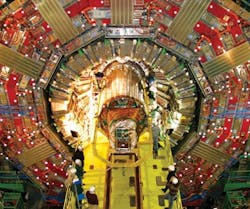
With a total surface area of 205 m², about the same as a singles tennis court, a silicon strip tracking detector was installed in CERN’s Compact Muon Solenoid (CMS) Experiment in Switzerland this past December. CERN is the European Organization for Nuclear Research (cern.ch).
The CMS Experiment, which has involved more than 500 scientists and engineers from 51 research institutions, uses a detector built around a huge solenoid magnet—a cylindrical coil of superconducting cable that generates a magnetic field of 4 teslas, about 100,000 times that of Earth.
Sensors Working Overtime
The world’s largest tracking detector has a surface area the size of a singles tennis court and uses 3,000 km of fiberoptic cable to transfer data.
Photo by CERN
Three families of signals are transferred from the heart of the detector to the back-end electronics, located in a dedicated service cavern. “The fibers and wires connect the front-end devices, such as readout chips, control electronics and all the rest of the various sensing elements, to the back-end electronics—the readout system and control system,” says Dr. Duccio Abbaneo of the CERN physics department.
The 40,000-channel Tracker fiber plant is a sub-detector of CMS. Digital control signals drive the readout electronics. Analog environmental signals are generated by temperature, humidity, current and voltage-sensing devices located inside the detector. Analog physics signals are generated by the tracking detectors. The control and physics signals travel on fibers, while the environmental signals travel on wires together with the power lines.
“The control signals and physics signals are transferred with the optical link,” says Abbaneo. “Opto-electrical conversion is performed inside the detector as close as possible to the readout ASICs and at the back end where signals are processed by the readout and electronic control boards.”
The environmental signals are transferred via electrical lines integrated with the power lines into custom-designed, multi-conductor cables, explains Abbaneo. “The cables are broken in a patch panel located outside the tracking volume but still inside the CMS detector,” he says. “In the section from the front-end electronics to the patch panel, about 5 m long and, partially inside the tracking volume, the power-carrying main conductors are made of an aluminum-based alloy to limit the mass inside the tracker. The section from the patch panel to the power supply racks, about 30 m long, has copper lines with larger total cross section, to minimize the impedance.”
Lines carrying the environmental signals are then routed from the power supply racks to the appropriate processing devices. In both types of cables, the data lines are shielded from the power lines within each cable, and an outer shield surrounds all the lines to screen the noise of the environment. “The importance of cable shielding has been proven experimentally, as the noise level in the physics data has been observed to depend, in some cases, on how and where the cable shields are connected to Earth,” explains Abbaneo.
Fiber, Fiber Everywhere
The system uses standard single-mode Corning SMF28 fiberoptic cable supplied by Ericsson as either single-fiber (approximately 40 km inside the Tracker), 12-way ribbon cable (approximately 24 km inside the Tracker) or 96-way multiribbon cable (approximately 30 km inside CMS). All fiberoptic cables have been pre-terminated with a variety of connectors or fiber lengths depending on the part of the system concerned. Three breakpoints exist in the system where custom patch-panels are designed to make installation of this large system easier.
Data transfer capacity of the Tracker fiberoptic system is specified and tested to be able to collect data from all 10 million detector channels of the silicon strip tracker at a rate of 100 kHz, the equivalent to 13 terabits/sec. “The links are assumed to operate for several thousand hours per year,” says Dr. Karl Gill, Abbaneo’s physics department colleague at CERN. “The individual fibers are nowhere near their intrinsic capacity, but the sheer number of detector modules requires a highly distributed system with many channels. These first raw data transferred out of the Tracker are then filtered, or zero-suppressed, by custom electronics boards, and only the particle signals and their addresses and time stamps are kept.”
About 50 Gbits/sec are transferred to the central data acquisition system via another CMS-wide system of fiberoptic cable, explains Gill. These data are filtered at various levels, and only about 5 MB/sec of Tracker data is stored permanently along with other data from the other CMS sub-detectors.
Analyze This
Environmental data, as well as information on the status of auxiliary systems such as cooling plants or nitrogen ventilation, are processed by the detector control system and the detector safety system to monitor the correct functioning of the detector and, in case of severe anomalies, trigger automatic actions such as switching off the power if overheating results from a failure in the cooling system, explains Abbaneo.
“Such data are stored in a dedicated database and also will be used for specialized analyses aimed at a precise characterization of the detector environment during data taking,” he says. “Finally, information on the status of the power system, readout system, control system and selected environmental information are used to define the data quality flags.” Data recorded with parts of the detector malfunctioning need to be flagged and discarded or processed in a special way, says Ball. If the detector anomalies were not registered and correctly accounted for, they could cause misleading interpretations of the data.
Longevity Matters
Because the detector is designed to operate without intervention for more than 10 years, it is designed to have a large redundancy. “If up to half of the channels, randomly distributed, were lost, significant tracking capabilities still would be retained,” says Abbaneo. “More-severe effects would be caused by a large loss of channels concentrated in a specific angular range. Special care has been taken in the design of subsystems that are identified to be particularly critical for the detector operation.” For example, intrinsic redundancy is implemented in the distribution of control signals to the front-end devices and in the power lines and cooling lines feeding the active thermal screen that separates the tracking volume from the electromagnetic calorimeter, which is crucial for the correct operation of both sub-detectors, he explains.
“Constructing a scientific instrument of this size and complexity, designed to operate at the LHC without intervention for more than 10 years, is a major engineering and scientific achievement,” says CMS spokesman Tejinder Virdee. “More than 500 scientists and engineers from 51 research institutions worldwide have contributed to the success of the project.”
Short-Range Signals
The silicon sensors are precision mounted on 15,200 modules that are in turn mounted on a very-low-mass carbon-fiber structure that maintains the position of the sensors to less than 100 µm, the diameter of a human hair.
“Each of the charged particles produced in LHC particle collisions at the heart of the CMS detector will be tracked with a precision of better than 20 µm,” says Sharp.
The digital control signals are transferred over short distances in electrical lines inside the detector, from the device where the opto-electrical conversion is performed to all the front-end devices served by a given control line, explains Abbaneo. “These lines need to be shielded very carefully since the digital signals, notably the 40 MHz clock, which ensures synchronous readout of all the detector channels, are picked up easily by the sensors, severely spoiling the quality of the data,” he says. “Small gaps in the shielding of control lines, such as where wires are soldered onto printed circuit boards, have detectable effects on the quality of the data, therefore needing special fixes.” The integrity of the digital signals themselves is ensured by active repeaters implemented on the lines where appropriate. Bit errors in the control lines can cause fatal misfunctioning in the readout electronics, says Abbaneo.
Patch-Panel Connections
The fiberoptic ribbons of the Tracker network arrive at a very dense and compact patch panel. There are 32 of these inside CMS for the Tracker, each of which can accommodate up to 1,920 fiberoptic channel connections, plus slack fiberoptic ends in a volume of 60x9x15 cm³.
“Ribbon/fanouts are terminated with sMU connectors by Sumitomo and MFS connectors by Diamond,” says Gill.
The fiberoptic connection at the compact patch panel uses a customized version of MFS connectors supplied by Diamond. “At the compact patch panel, eight ribbons are connected to 96-channel multi-ribbon cable,” continues Gill. “This is a custom cable with 8x12-way ribbon stack, strength members and low-smoke, zero-halogen jacket, MFS connection at one end and MPO at the other.”
“The multiribbon cables run the 55 m distance from detector in the experimental cavern through tunnels to the service cavern where data treatment is done in a custom data-acquisition system with analog-to-digital conversion, zero-suppression and filtering of the interesting physics data from an enormous background that includes less-interesting proton-proton collisions inside the detector,” he says.
COMING NEXT
Our Q2 (May) 2008 issue will explore factory/networking integration. Tying together plant-floor, enterprise, physical security, building and other networks is more prevalent than ever. However, linking all these systems means even more chances for unauthorized access. This article will show how users are solving these problems, and we could use your experiences, too. To contribute, please e-mail [email protected].
Correction
The eighth product that appeared in Industrial Networking Winter 2008 Products was misidentified. It is the Rosemount Analytical Model 1056 Intelligent Dual Input Analyzer from Emerson Process Management.

Leaders relevant to this article:


