IEC 61131-3 specifies syntax and semantics for a unified suite of programming resource


IEC 61131-3 is the first real endeavor to standardize programming languages for industrial automation. With its worldwide support, it is independent of any single company.
The third part of the IEC 61131 family, it is a specification of the syntax and semantics of a unified suite of programming languages, including the overall software model and a structuring language.
Another elegant view can be seen by splitting the standard in two parts—common elements and programming languages.
Common elements—data typing
Within the common elements, the data types are defined. Data typing prevents errors in an early stage. It’s used to define the type of any parameter used. This avoids for instance dividing a date by an integer.
Common data types are Boolean, Integer, Real and Byte and Word, but also Date, Time_of_Day and String. Based on these, you can define your own personal data types, known as derived data types. In this way you can define an analog input channel as data type and reuse this over and over again.
Common elements—variables
Variables are only assigned to explicit hardware addresses, such as. inputs and outputs, in configurations, resources or programs. In this way a high level of hardware independence is created, supporting the reusability of the software.
The scope of the variables is normally limited to the unit in which they are declared—for example, local. This means their names can be reused in other parts without any conflict, eliminating another source of errors. If the variables should have global scope, they have to be declared as such. Parameters can be assigned an initial value at startup and cold restart, in order to have the right setting.
Common elements—configuration, resources and tasks
To understand these better, let’s look at the software model, as defined in the standard (Figure 1).
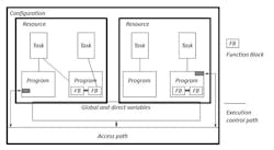
Figure 1: The entire system required to solve a particular control problem can be formulated as a configuration.
At the highest level, the entire system required to solve a particular control problem can be formulated as a configuration, including the arrangement of the hardware, memory addresses for I/O channels and system capabilities.
Within a configuration, you can define one or more resources. You can look at a resource as a processing facility that is able to execute IEC programs.
Also read: The Case for PackML
Within a resource, one or more tasks can be defined. Tasks control the execution of a set of programs and/or function blocks. These can either be executed periodically or upon the occurrence of a specified trigger, such as the change of a variable.
Programs are built from a number of different software elements written in any of the IEC-defined languages. Typically, a program consists of a network of functions, such as ADD, ABS, SQRT, SINus and COSinus, and function blocks, which are able to exchange data. Function and function blocks are the basic building blocks, containing a data structure and an algorithm.
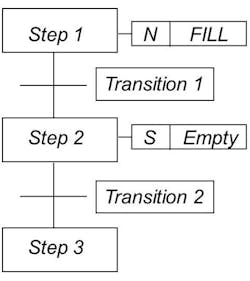
Figure 2: An SFC consists of steps linked with action blocks and transitions. Each step represents a particular state of the system.
Function blocks contain data, as well as the algorithm, so they can keep track of the past. They have a well-defined interface and hidden internals, such as an IC or black box. In this way they give a clear separation between different levels of programmers or maintenance people.
A temperature control loop, or PID, is an excellent example of a function block. Once defined, it can be used over and over again in the same program, different programs or even different projects. This makes them highly reusable.
Function blocks can be written in any of the IEC languages and, in most cases, even in C or C++. In this way they can be defined by the user.
A conventional PLC contains one resource, running one task, controlling one program, running in a closed loop. IEC 61131-3 adds much to this, making it open to the future—a future that already includes multi-processing and event-driven programs.
IEC 61131-3 is suitable for a broad range of applications, without having to learn additional programming languages.
Common elements—sequential function charts
A sequential function chart (SFC) describes graphically the sequential behavior of a control program. With this, it structures the internal organization of a program and helps to decompose a control problem into manageable parts, while maintaining the overview (Figure 2).
An SFC consists of steps linked with action blocks and transitions. Each step represents a particular state of the system. A transition is associated with a condition, which, when true, causes the step before the transition to be deactivated, and the next step to be activated. Steps are linked to action blocks, performing a certain control action. Each element can be programmed in any of the IEC languages, including SFC itself. You can use alternative sequences and parallel sequences, commonly required in batch applications.
Because of its general structure, an SFC also provides a communication tool for people of different backgrounds, departments or countries.
Programming languages
Within the standard, four programming languages are defined. This means that their syntax and semantics have been defined, leaving no room for dialects. Once you have learned them, you can use a wide variety of systems based on this standard. The languages consist of two textual and two graphical versions.
Textual versions include instruction list (IL) and structured text (ST). Graphical versions include ladder diagram (LD) and function block diagram (FBD)
All four languages describe the same simple program part (Figure 3). The choice of programming language is dependent on:
- the programmer’s background
- the problem at hand
- the level of describing the problem
- the structure of the control system
- the interface to other people or departments.
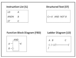
Figure 3: All four IEC 61131 languages describe the same simple program part.
Ladder diagram has its roots in the United States. It is based on the graphical presentation of relay ladder logic.
Instruction list is its European counterpart. As a textual language, it resembles assembler.
Function block diagram is very common to the process industry. It expresses the behavior of functions, function blocks and programs as a set of interconnected graphical blocks. It looks at a system in terms of the flow of signals between processing elements.
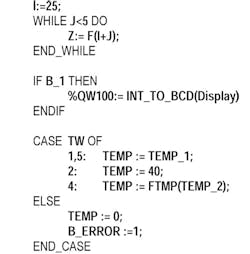
Figure 4: Structured text can be used for the definition of complex function blocks, which can be used within any of the other languages.
Structured text is a very powerful high-level language with its roots in Ada, Pascal and C. It contains all the essential elements of a modern programming language, including selection branches (IF-THEN-ELSE and CASE OF) and iteration loops (FOR, WHILE and REPEAT). It can be used excellently for the definition of complex function blocks, which can be used within any of the other languages (Figure 4).
The 3rd edition and object oriented features
With the release of the 3rd edition in 2013, object oriented features were added to the specification. With this, classes, method, interfaces and namespaces became part of the specification, all linking it to a new generation of software programmers, as well as to other software tools.
Conclusion
The technical implications of the IEC 61131-3 standard are high, leaving enough room for growth and differentiation. IEC 61131-3 impacted the whole industrial control industry: not only the conventional PLC market, but also the motion control market, distributed systems and soft-logic/PC-based control systems, including PACs. And the areas, including safety, communication and exchange, are still growing.
Having a standard over such a broad application area, brings numerous benefits for users and programmers. The benefits for adopting this standard are various, depending on the application areas. They include:
- reduced waste of human resources, in training, debugging, maintenance and consultancy
- creating a focus to problem-solving via a high level of software reusability
- reduced misunderstanding and errors
- programming techniques usable in a broad environment: general industrial control
- combining different components from different programs, projects, locations, companies and/or countries.
