12 steps to Li-Fi implementation
A plant’s communication system is an important part of its total capital expenditure on instrumentation. Conventional wiring systems involve cables and infrastructures, such as junction boxes, conduits, termination racks, cabinets, marshalling panels, enclosures, cable trays and conduits, which in turn increase the capital costs and pose potential problems during installation and modification.
One alternative is a Wi-Fi-based instrument communication system, which eradicates the problem of cable infrastructure, as it’s completely wireless, but raises security concerns such as remote jamming, cyber attacks, phishing and RF spectrum.
Light fidelity (Li-Fi) is an attempt to combine the advantages of both systems and provide a more reliable and cost-effective option.
Next-generation plant communication system
Optical wireless field instruments, optical access points (OAPs), transceiver modules, fiberoptics and Ethernet media converter modules comprise our Li-Fi instrument communication network. Multiple control network switches are installed in communication cabinets and distributed control systems (DCSs) in the control room or substation.
Optical wireless instruments (OWIs) should be located either inside or outside of the module in the process area of plants. These OWIs are used to measure/control the process variables of the plants.
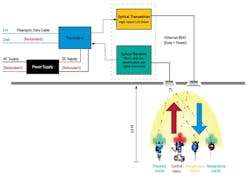
Optical access points (OAPs)/transceiver modules should be deployed inside the closed module in the ceilings and either in the outside platform or in the structure platform/grating/support for the outside of the module and/or open module. OAPs can be connected to fiberoptics/Ethernet media converter via redundant Ethernet cable (copper, twisted pair, Cat. 5), RJ45 or 8P8C connector to convert fiberoptic media into Ethernet and vice-versa.
Fiberoptics/Ethernet media converter modules should be located in the field and/or module to facilitate the media conversion between fiberoptics and Ethernet.
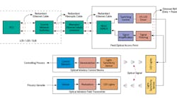
A redundant fiberoptic cable should be routed in separate divergent routes to connect the field-installed OAPs and control network switches installed in an industrial-control-system (ICS) communication cabinet (Figure 1).
Figure 1: A redundant fiberoptic cable should be routed in separate divergent routes to connect the field-installed OAPs and control network switches installed in an industrial-control-system (ICS) communication cabinet.
A redundant Ethernet cable connects ICS communication cabinet and DCS/PLC systems in the local control room (LCR), local electrical room (LER) or substation (SUB).
Optical wireless field instruments
Optical wireless transmitters are constituted by a sensor for real-time measurement of process variable information and the timely transmission per update rate of OWI to the OAP via optical signal.
Optical wireless control elements are constituted by the control element and the light-sensitive module, which receive the optical signal at the light-sensitive sensor and convert it into a respective electrical signal to control the process variable.
Optical access point (OAPs)/transceiver modules comprise LED lights, light-sensitive sensors such as photo-detector or solar-panel, high-speed LED drivers, amplification and processing modules and power modules. The light-sensitive sensor is connected to an optical receiver or signal processing and amplification module, which processes the process-variable information transmitted from the optical wireless transmitters and sends to the DCS/PLC in the LCR/LER/SUB via redundant fiberoptic cable. The switch control module converts the control signal from the DCS/PLC into a switching signal of a specific frequency. The high-speed LED driver receives the switch signal, which is converted to LED flashing lights—optical signal. Intrinsically safe battery packs or renewable energy, such as thermal, solar, vibration/wind, power the light-sensitivity sensor module, LED array and processing module.
Building the Modular Li-Fi Instrument communication network requires 12 steps.
Step 1: The transmitter sensor module—temperature, pressure, level, flow—measures the real-time process variables in the plant. The real-time process-variable information will be sent to the nearby optical access point (OAP) via optical signal—transmitted light, not radio signal. The process variable information shall be updated to the OAP or DCS, as per the user-defined update rate. The update rate of the optical wireless instruments will be decided on the basis of loop criticality of the process.
The optical transmitter module measures the real-time process-variable information, and the process-variable value is sent to the transmitter control module via hardwire signal.
The transmitter control module processes the process-variable value and converts it into a certain frequency of the switching signal. This encoded switching signal drives the high-speed LED driver, which controls the switching of LED lights to create the optical signal transmitted to the corresponding optical access points (OAPs).
Step 2: The light-sensitivity sensor of the OAP, senses the flickering or change in intensity modulation or on-off frequency of LED lights and converts the optical signal from the field optical transmitter into a corresponding electrical signal. Then the output of the light-sensitive sensor is sent to a signal processing and amplification module.
Step 3: The signal-filtering, -processing and -amplification module receive the output electrical signal from the light-sensitive sensor module for filtration, amplification, analysis and processing. Then the amplified signal is sent to the Ethernet media conversion module.
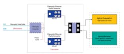
Step 4: The Ethernet media conversion module is used to facilitate the amplified electrical media conversion into a fiberoptic-compatible optical signal, or light signal. Then this optical signal is sent to the control room/local substation via redundant fiberoptic cable (Figure 2).
Figure 2: The Ethernet media conversion module is used to facilitate the amplified electrical media conversion into a fiberoptic-compatible signal. Then this signal is sent to the control room, electrical room or local substation via redundant fiberoptic cable.
Step 5: The fiberoptic cable (FOC) connects the field optical access point (OAP) to the LER communication control switch network. The ICS communication cabinet consists of multiple control switches, which convert the received optical signal from a field optical access point into the corresponding Ethernet-compatible electrical signal.
Step 6: The ICS communication cabinet is connected to the DCS via redundant Ethernet cable—copper, twisted pair, Cat. 5—or RJ45 or 8P8C connector. The DCS receives the electrical signal from the field instrument for processing and sends the field process-variable information to the display module. The display module presents the process-variable information to the engineering workstation (EWS) or operator workstation (OWS) for further action.
Step 7: After analysis of the process-value information from the field optical instrument, the appropriate control action signal is generated by the DCS to control the process in the plant. The control signal is sent to the ICS communication cabinet via Ethernet cable.
Step 8: The ICS communication cabinet contains multiple control network switches to facilitate the media conversion from Ethernet to fiberoptic-compatible. The fiberoptic cable carrying the corresponding control signal in the form of an optical beam, or light beam, is sent to the field optical access point followed by fiberoptic/Ethernet media conversion.
ALSO READ: DHS cybersecurity director on avoiding security vulnerabilities when connecting to the IIoT
Step 9: The received control signal from the DCS to the fiberoptic/Ethernet media conversion, located in the field and/or module, converts the optical signal media into an Ethernet-compatible corresponding electrical signal. This electrical signal carries control-action information to the OAP.
Step 10: The OAP receives the control signal from the DCS located in the LCR/SUB via redundant fiberoptic/Ethernet cable. This electrical signal is further encoded in a certain frequency of the switching signal. This switching signal is further sent to the high-speed LED light driver.
Step 11: The high-speed LED light driver regulates the intensity modulation of the LED lights, which is not observed by human eye, as per the received encoded switching signal. The optical access point emits the control signal in the form of an optical signal, which is further received by the control device, such as a valve.
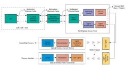
Step 12: The received optical signal carries action information of the final control element and is further converted into an electrical or pneumatic or hydraulic signal to control the process (Figure 3).
Figure 3: The received optical signal carries action information of the final control element and is further converted into an electrical or pneumatic or hydraulic signal to control the process.
Implementation
The implementation of light-fidelity (Li-Fi) eliminates the use of instrument wiring systems and cable infrastructure, thereby reducing the cost and security risks. The Li-Fi instrument communication networks are best-suited for plants where Wi-Fi and other radiation is bad for sensitive areas. It offers safe, abundant connectivity and can solve issues related to the short range of radio-frequency bandwidth. The Li-Fi instrument communication network also could enable greater capabilities to realize the Industrial Internet of Things (IIoT) and offer advanced connectivity between field devices and systems that go beyond machine-to-machine connections. The system has relatively low capital expenditure (CAPEX) and operating expenses (OPEX).

Leaders relevant to this article:
