
Programmable logic controllers (PLCs) and ladder logic programming have enjoyed wide acceptance in the discrete manufacturing and process industries since their introduction during the 1970s.
SEE ALSO: Algebraic Solution Beats Fuzzy Logic
Perhaps less well known is the manner by which ladder logic can be transitioned to fuzzy logic. There often are clear benefits to using fuzzy logic instead of more conventional methods of control. Like ladder logic, fuzzy logic is also a type of rule-form logic. It has been developed to solve problems that are difficult to define or model with ladder logic.
Each rung in a ladder logic program represents a discrete or binary logic equation. On the far right side of each rung is a symbol indicating the output condition. This condition is set depending on the outcome of the "IF" conditions represented by all of ladder logic symbols to the left of the output symbol. Thus, the far right side symbol signifies the "THEN" result generated by combining all of the left side IF symbols.
With fuzzy logic structure, membership functions are used to describe how much "truth" a given input has in a condition statement. The amount of truth is expressed as a value from 0 to 1. IF-THEN rules are used to determine final output values.
Fuzzy logic is a natural extension to binary logic for industrial controls, but to use it properly requires an understanding of practical control considerations, fuzzy logic design tools, and how the control system behaves under various conditions.
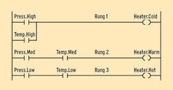
The ladder program in Figure 1 describes control of a three-stage heater with sensor feedback inputs of pressure (Press) and temperature (Temp). Note that the output variable Heater can assume three discrete levels: Cold, Warm and Hot.
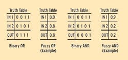
Rung 1 of Figure 1 shows there is no power to the heater (Heater.Cold is true) if either the pressure is high or the temperature is high. If both pressure and temperature are high there is also no power to the heater. If we associate a 1 with a true condition and a 0 with a false condition, then Rung 1 can be expressed as the Binary OR truth table shown in Figure 2.
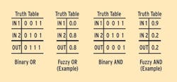
In a similar manner, Rungs 2 and 3 can be expressed as logical AND statements and represented by the truth table labeled Binary AND, shown in Figure 2. Note that in the OR logic statement the variable with the largest value (maximum) controls the output, while in the AND logic statement, the variable with the smallest value (minimum) controls the output.
Analog Thinking
Referring again to Figure 1, the binary parallel contacts Press.High and Temp.High in Rung 1 could be replaced by analog sensor inputs connected in parallel as shown in Rule 1 of Figure 3. Rung 1 in Figure 1 is converted to Rule 1 in Figure 3 because ladder logic rungs are similar to fuzzy logic rules.
In Figure 1, if the pressure is High or if the temperature is High, then the output is fully energized, and there is no power provided to the heater. If we use analog sensor inputs as shown in Figure 3, the temperature and pressure can now be expressed as analog values. In this example, the temperature high test provides a value of 0.8 and the pressure high test provides a value of 0.0.
Note that the raw analog values provided by the sensors have to be mapped against the defined membership functions of the fuzzy controller. The result of this mapping then yields the input values for the fuzzy rules. This mapping process is called fuzzification, and it's explained below.
The digital values in rungs 2 and 3 of Figure 1 can also be replaced by analog values as shown in Rules 2 and Rule 3 in Figure 3. These analog values can then be inserted in a Fuzzy AND table as shown in Figure 2.
Note that serial inputs are solved by an AND truth table, while parallel inputs are solved by an OR truth table. This is true for both ladder logic rungs and fuzzy logic rules.
In the Binary AND truth table as well as in the Fuzzy AND truth table, the smallest of the input values equals the output value, so the output value is 0.2 for Rule 2 and 0.0 for Rule 3. These truth table results are shown as the Rule 2 and Rule 3 outputs in Figure 3.
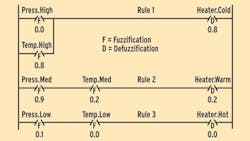
As we look at the values of these three outputs, it is intuitive that the heater should be at a very low power setting. This is because the Heater.Cold output has a much larger value (0.8) than the Heater.Warm output (0.2) and the Heater.High output (0.0).
Rule Generation
The fuzzy ladder diagram in Figure 3 can be used to generate these fuzzy logic rules:
- if Press.High or Temp.High then Heater.Cold
- if Press.Med and Temp.Med then Heater.Warm
- if Press.Low and Temp.Low then Heater.Hot
These rules also describe the logic of Figure 1. However, in Figure 1, only one output can be activated at any one time, resulting in three discrete heater power levels. In Figure 3, all rules contribute simultaneously according to their momentary weight resulting in continuous or analog heater control.
In essence, the three rules address a desired heater response in specific regions. With ladder logic control these regions change abruptly, while with fuzzy logic control one region blends smoothly into the other. This smooth rather than abrupt control is one of the advantages of fuzzy logic over discrete logic.
Fuzzification
In discrete logic, threshold detectors are used to decide if a temperature is medium or high. As such, a very sharp or vertical threshold line separates the two states. In fuzzy logic this threshold is tilted like a ramp function to describe the gradual change from true to false. These tilted threshold functions are called membership functions.
Figure 4 illustrates fuzzification, which is the mapping of an input variable against the membership functions. These membership functions are user-definable, and are shown by the three lines marked Low, Med and High.
The Low, or leftmost membership function is shown by the line that runs from 1.0 on the vertical axis to a value of about 150° on the horizontal axis. The Med membership function is triangular in shape and depicted by the dot-dash line. The High, or rightmost membership function starts at about 150° on the horizontal axis, increases to a value of 1.0 on the vertical axis, and terminates on the horizontal axis.
In the example, a temperature of 170° maps into a value of 0.8 against the membership function High, and at the same time maps into a value of 0.2 against the membership function Med. The membership function Low is outside the range, and thus returns a value of 0.0.
The vertical dashed line shows the pressure sensor input variable and how it produces a value of 0.1 for Press.Low, a value of 0.9 for Press.Med, and a value of 0.0 for Press.High. The actual pressure sensor values along the horizontal axis are similar to the temperature scale, but are not shown here to keep the figure simple.
These mapped values of temperature and pressure are used in Figure 3 instead of the raw analog sensor values.
Figure 4: Fuzzification Rules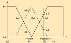
Defuzzification
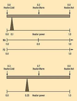
Defuzzification is the mechanism of drawing a conclusion from the various rules concerning the same output variable. The three rules shown graphically in Figure 3 address the same output variable Heater. In this example, the fuzzy logic illustrated in Figure 3 yields output values of 0.8 for Heater.Cold, 0.2 for Heater.Warm, and 0.0 for Heater.Hot.
The weighted average (WA) method can be used to calculate the value of the heater output. The equation for a weighted average calculation is shown below:
Figure 5 is a graphical representation of this equation. The WA equation is best visualized as putting the different output contributions at their assigned places as weights on a balance beam, and finding the support point for equilibrium.
A weight of 0.8 on the left wing and a weight of 0.2 at the center places the support at 0.1 if the beam has a length of 1.0 from left to right. This final output (FO) value of 0.1 indicates that the heater is operating at 10% of capacity.
Changes in the input values of temperature and pressure could change the outputs to 0.3 for Heater.Cold, 0.7 for Heater.Warm, and 0.0 for Heater.Hot, also shown in Figure 5. This would then move the support beam to a value of 0.35. This FO value of 0.35 indicates that the heater is operating at 35% of capacity. The FO value can also be calculated using the equations shown above.
By looking at the defuzzification model, a number of observations can be made:
- The relative weight, not the absolute weight, controls the output.
- At least two weights must be placed at different locations on the beam, and at least one of the weights must be less than 1.0 (not saturated).
- If only one weight is present, then the support point is directly under that weight no matter how heavy the weight is.
- If no weight is present, the output is undefined. If no rule contributes, the output is not zero but undefined.
Why Fuzzy?
In conventional closed-loop control, only one input variable (and maybe its derivative) is used to control an output. Fuzzy logic is especially useful if two or three distinctly different and interactive input variables participate in the control of an output.
Consider a water tank with a heater, a temperature sensor, a pressure sensor, and a flowmeter. The flowmeter shows the rate at which hot water is withdrawn from the tank. As water is withdrawn, the tank is continuously refilled with cold water to hold a constant level. This is similar to the example just discussed with the addition of the dynamic flows into and out of the tank.
The flowmeter does not contain any temperature information, and its operation is not affected by water temperature. However, when hot water is withdrawn from the tank at a high rate, then strong heat must be applied because cold water is coming in quickly, cooling down the tank. This gives the flow rate some of the characteristics of a temperature derivative.
An additional rule could be included with the ones already given in Figure 3:
- if Flow.High and Press.Low then Heater.Hot
All four rules now control the heater simultaneously. Note that if the flow is reduced, this rule fades away to a zero output and its contribution to the result disappears. This type of intuitive control is hard to implement with conventional analog and discrete control systems.
Many readers will recognize we could have controlled the heater in the initial example in a continuous fashion without resorting to fuzzy logic. A relatively simple analog inner-loop control system could have been devised to provide much the same type of control.
However, to include pressure and/or flow modifiers, additional outer-loop control would be necessary to modify the temperature setpoint of the inner loop. This adds considerable complexity to the control system. In many instances this complex analog control system would not perform as well as a relatively simpler fuzzy logic control system.
There are many other industrial temperature control applications where fuzzy logic will yield much better control than other types of advanced control. For example, in plastic molding applications there are heating coils, but compression of the plastic material also generates heat. These multiple-interacting variables are well-suited to fuzzy logic control.
In general, fuzzy logic should be considered for any system where two or more different and interactive input variables participate in the control of an output.
REFERENCES
1. Allen-Bradley, "PLC-5 Programming Manual," Allen-Bradley Co.
2. Zadeh, L.A., "Outline of a New Approach to the Analysis of Complex Systems and Decision Processes," IEEE Trans. Syst., Man., Cybern., vol SMC-3, no.1, pp 28-44, 1973
3. Struger, O., S. Chand and E. Dummermuth, "Fuzzy Logic and Programmable Logic Controllers," Annual Conference of ISA, Instrument Society of America, October 1991
4. Day, C.P., and E.H. Dummermuth, "Practical Considerations of General Fuzzy Logic Controls for Industrial Applications," Joint IEEE Regional Aerospace Control Conference and Rockwell Intl. Fifth Annual Conference on Control and Signal Processing, May 25, 1993.
5. Day, C.P., and E.H. Dummermuth, "Logical Industrial Controls Using Fuzzy Rules," The Third International Conference on Industrial Fuzzy Control and Intelligent Systems, December 3, 1993.
6. E. H. Dummermuth, "The Real Issues in Fuzzy Logic Applications," IRTC '94 Symposium on Artificial Intelligence in Real-Time Control, Oct. 3-5, 1994
7. J.M.Mendel, "Fuzzy Logic Systems for Engineering: A Tutorial," Proceedings of IEEE, vol.83(3), 1995
8 . F. Herrera and M. Lozano, "Adaptation of Generic Algorithm Parameters based on Fuzzy Logic Controllers."
9. Genetic Algorithms and Soft Computing, Physica-Verlag, pp 95-125, 1996
10. D.F. Akhmetov and Y.Dote, "Fuzzy System Identification with General Parameter Radial Basis Function Neural Network." In Fuzzy Control: Synthesis and Analysis, S.S.Farinwata, D.Filev and R.Langari (Eds), Chichester, U.K: John Wiley & Sons, 1999.
11. S. Satoh, M.S. Shaikh, Y. Dote, Muroran Institute of Technology, Japan, "Fast Fuzzy Neural Network for Fault Diagnostic of Rotational Machine Parts using General Parameter Learning and Adaptation." IEEE Mountain Workshop on Soft Computing in Industrial Applications, June 25-17, 2001.
12. P. Dadone and H.F. VanLandingham, "Remote Control of Industrial Processes." IEEE Mountain Workshop on Soft Computing in Industrial Applications, June 25-17, 2001.
13. E. H. Dummermuth, "A Non-Linear Tunable PI Block for Improvement of Closed-Loop Control Response," IEEE Mountain Workshop on Soft Computing in Industrial Applications, June 25-17, 2001.
