JUST ABOUT every machine, robot, and skid builder OEM uses Computer Aided Drafting (CAD) to some degree to create the drawings needed to build its products. The use of CAD to expedite and improve product design is a given these days, but this was not always the case.
As recently as the late '80s, CAD applications were considered too complex and expensive for many machine builders. There were many skilled board drafters who understood machine, robot, and skid design from both a mechanical and an electrical perspective. It was very hard to find people who understood machine builder needs, and who also knew how to navigate complex CAD software.
CAD software was very expensive, filled with bugs, and the hardware to run it was pricey. Substantial investments that many industrial OEMs just had made in PCs were not sufficient for CAD software, so new or upgraded hardware was required. Printers capable of producing quality drawings were large, finicky, and very expensive.
We all know how this story eventually unfolded. CAD software improved, PC price/performance ratios leaped ahead, and designers jumped on the CAD bandwagon. Virtually all industrial OEMs now use some form of CAD to produce drawings, and many also use CAD add-ons to automatically generate related electrical design drawings such as wiring diagrams, I/O ladder drawings, and panel layout drawings. The CAD dilemma has been solved. CAD won and manual drafting lost.
A New Chapter: Advanced CAD
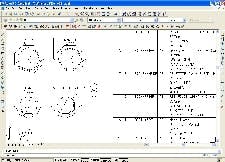
A few years ago, another story began, and CAD again is a participant. It involves what might be called advanced CAD, and it encompasses the use of CAD to accomplish high-level functions such as collaboration among machine builders, their customers, and vendors. It also uses CAD to perform complex functions such as automatic drawing and document generation, and automatic on-line updates of multiple cross-referenced drawings and documents (See Figure 1 below).
AutoCAD was used to automatically generate a bill of materials for this control panel.
Collaborate With CAD
CAD enables industrial OEMs, customers, and vendors to collaborate in ways that were not possible or too unwieldy to manage with manual drawings. Chief among these collaborative tools is the simple but effective function of sending drawings via e-mail.
"The ability to transfer electronic files from one work station or vendor to another and obtain near immediate feedback is extremely important," says Michael Weigandt, vice-president/CTO of Osgood Industries. "This helps reduce the cost of manufacturing, shortens the time required for design, and minimizes lead-time for new product launches or incremental improvements to existing products."
Osgood Industries is a design/build fabricator of filling, sealing, and capping systems used primarily in the fresh, refrigerated food industry. The company is longtime user of AutoCAD software for control panel design. "Another benefit of using CAD in our design process is the ability to integrate our drawings into the total scope of the factory automation system where our products are installed," adds Weigandt. "Our customers and their system integrators now can perform in seconds what used to take days or even weeks to accomplish."
File sharing via e-mail has come along way in the past few years because of high-speed Internet connectivity. Downloading CAD files over a phone modem is possible, but large files download slowly at best and not at all at worst.
Even though many e-mail servers limit the size of e-mails and attachments, very large files can be transferred by posting to a web site. The URL where these reside can then be e-mailed to others so they can access and download information more easily.
Good Reasons to Use Advanced CAD
- Automatic generation of drawings and documents.
- Automatic propagation of changes throughout the project drawing and document set.
- Quick exchange of design details with vendors and customers.
- Audited control of drawings and documents.
- Instant on-line quotes for machined parts.
- Comprehensive on-line design reviews with 3-D CAD software and viewers.
A huge advantage of file sharing via the Internet and e-mail is near instantaneous information transfer, even internationally. "CAD is very beneficial when collaborating on machine designs with our parent and sister companies in Germany and Brazil respectively," says Rod Kettels, controls designer with Grob Systems. "All three companies can share the same drawing standards and designs quickly and easily, which eliminates repetition, reduces errors, and saves time."
Grob Systems produces automation, assembly, and metal-cutting machines for companies involved in powertrain component production, and for companies producing components that require special machining and automation. Grob uses EPlan CAD software to produce its mechanical and electrical drawings.
A more sophisticated approach to file sharing is employed by Automation Tooling Systems. ATS designs and builds advanced factory automation systems, custom automation equipment, standard automation products, and turn-key assembly machinery.
eDrawings takes this concept a step further. According to SolidWorks, eDrawings produces simple graphical representations CAD drawings that can be viewed and marked up via the Internet through a standard web browser. Users do not need to purchase or install any separate tools or CAD software. Besides SolidWorks, the eDrawings plug-in is also available for AutoCAD and PTC/ProEngineer. eDrawings also can be used as a viewer for native SolidWorks, .dxf, and .dwg files.
"Our customers use the markup functionality of eDrawings to convey their thoughts about the design of our machines," observes Mike Baljak, mechanical designer with ATS. "These markups are captured inside the e-drawing, and we use these comments to adjust the design. This process makes collaborating with our customers cost-effective and shortens our design cycle time."
Intergraph's SmartPlant Review supports worldwide workgroup collaboration and file format interoperability. Its customers use SmartPlant for various tasks ranging from routine reviews of 3D models to planning efficient layout of factory floors in a variety of industries including automotive, turbine fabrication, and pharma plant batch process setups.
Vendors Share With CAD
Remember the old days of control panel and electrical design? A designer needed detailed drawings of each electrical or control component, and then manually had to transfer relevant information from each drawing to design drawings.
Nowadays, many electrical and control component vendors use electrical and control systems CAD software to produce component drawings. OEM engineers and designers then can access these drawings from a vendor-supplied CD or the web.
AutomationDirect, Phoenix Contact, and Schneider Electric all use promis-e, an AutoCAD add-on from ECT Intl. to transfer component design information to customers.
According to ECT, promis-e provides specialized tools and functions for designing and documenting control systems. It provides pre-defined page formats for ANSI and IEC standard drawings, and symbol libraries also are available for electrical, hydraulic, pneumatic, and process control applications.
"Our customers use promis-e to create the layout, wiring diagrams, and design of their control cabinets; and in the process select the AutomationDirect components that are part of their system," says Gary Marchuk, director of business development at AutomationDirect. "At the conclusion of the design, the designer prints a bill of materials and faxes it to us. As we grow further in the area of collaboration, we would like to link the promis-e software to our web store to directly populate a shopping cart."
Phoenix Contact uses promis-e to provide its customers an up-to-date CAD database with all required dimensions, shapes, and products used in electrical, instrumentation, and control applications. "The ongoing development of a CAD parts database allows our new products to be applied sooner, and comparison to existing or legacy components can occur more easily," says Arnold Offner, international committee manager with Phoenix Contact. "The benefits to our customers are time reduction in engineering changes, ease of comparison to other parts, and the ability to verify all dimensional parameters sooner."
FIGURE 3: BUILDER, SUPPLIER COLLABORATION
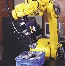
The design software used for Fanuc intellgent robots integrates supplier/partner product databases for automatic component selection in the bills of material.
Schneider Electric makes promis-e an integral part of its new Unity collaborative automation software, which automatically generates electrical system CAD drawings. The software creates supporting documentation such as bills of material, wiring lists, terminal block plans, panel layouts, wiring diagrams, cable schedules and interconnect/raceway information automatically from the project database.
Put It on Autopilot
Why would anyone want to perform mundane tasks manually when an automatic alternative exists? This is the question that many machine builders ask themselves as they consider software products that automatically generate a multitude of project documents and drawings from a few basic design drawings.
The benefit of auto generation is clear. Data is entered one time only, and multiple drawings and documents are generated from these data. Matt Bothe, senior automation engineer with CRB Consulting Engineers, reports that his firm implemented auto generation on a recent project. "We started from a set of data-centric P&IDs, from which all relevant instrument data was transferred to a database application," says Bothe. "From the database application, supplemental data from pipe specifications, general arrangement drawings, user requirements, and vendor literature was added."
The algorithms within the database application enabled automatic generation of vendor lists, routing strategies, and datasheets slated for review, bid, and/or procurement. "Although some supplemental data was manually entered, the bulk of the data required to define an instrument and associated inter-connects was automatically entered," adds Bothe.
CRB recently developed and successfully tested auto generation of AutoCAD-compatible wiring and loop diagrams from the database application. With proper link data entered into the application, AutoCAD-compatible drawings can been prepared from what CRB calls drawing templates.
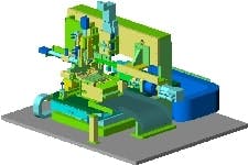
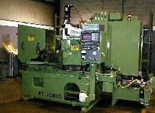
Machine Tool Specialists used CAD software as a design tool to rebuild this microcentric grinder, and re-use pertinent data into the newer design from the older version.
Change Once, Propagate to Many
One of the main characteristics of electrical, control, and instrumentation drawings is the repetition and inter-relation of data from one drawing or document to the next. The simple task of changing one letter of one tag on a piping & instrument diagram (P&ID) drawing can be fiendishly complex if this data is to automatically propagate to all related drawings and documents.
Unfortunately, the alternative to automatic propagation is also problematic. Manual updating of all related drawings and documents is a tedious and time-consuming process fraught with error.
The CRB Consulting example illustrates auto-generation of drawings and documents from a data-centric P&ID and a database. CRB also uses these same tools to automatically propagate changes throughout their design documents and drawings. "For properly configured data transfers, changes originating at the P&ID level may be readily transferred to the instrument database without corrupting or losing existing data," states Bothe. "Systematic or broad changes are implemented easily, without updating each record individually."
Auto-propagation at CRB is accomplished with a combination of custom software development and off-the-shelf CAD software. Auto-propagation also can be implemented entirely with off-the-shelf products.
ECT Intl.'s promis-e software enables cross-referencing to encompass hundreds or thousands of pages of drawings. When the designer working on one page makes a change, that change is reflected in real time to those working on other pages, through cross-referencing and duplicate ID checking.
EPlan also provides auto-propagation with its CAD software. "The interconnectivity of individual data means that an amendment on one page often leads to an amendment on another," says Sean Patrick Mulherrin, technical manager at EPLAN. 'With EPlan, each modification in the schematics results in automatic updating, thereby eliminating the need to manually rewrite or edit bills of material, wiring list, terminal and connector allocations, page numbering, table of contents, and so on."
Should You Jump In?
The benefits of advanced CAD are pretty clear, but the costs are substantial and the pitfalls are many. Perhaps the biggest problem with implementation of advanced CAD is the many different CAD packages now used by machine builders.
Are You Sure You're Ready for Advanced CAD?
- Prepare to spend more on software, both up front and on annual licenses.
- Be aware that advanced functionality often is lost if files are translated to other formats.
- Collaboration with other firms works best when all use the same advanced CAD products.
- Considerable training and aptitude are necessary to implement advanced CAD.
- Advanced CAD often requires upgrade hardware.
There are certain "standard" CAD file formats such as .dwg and .dwf that can be read and produced by almost every CAD package. Unfortunately, advanced functions are usually lost in translation, and full benefits of CAD might be realized only when all project participants standardize on the same revision of the same software package.
"If each member of the team is using different CAD packages or even different revisions of the same package, design approval and modification is cumbersome," says Piotrowski of Fanuc Robotics America. "CAD software allows the user to save the drawings in a variety of formats, but some simply are not compatible with others. The entire design process--from initiation to final release--flows much more smoothly if everyone involved is using the same revision of the same CAD software."
Kettels of Grob Systems agrees. "Each CAD software package has its own non-compatible standards and file types," he says. "One solution is to export drawing files into an AutoCAD .dwg/dxf format, but this practice defeats the purpose of collaborative design software because valuable information developed and contained in each drawing is lost when any kind of export function is executed."
Incompatibility is a problem, and so are costs. "CAD software licenses are relatively expensive," adds Weigandt of Osgood Industries. "The software is constantly being upgraded, ultimately leading to a time when older generations no longer are supported. The hardware necessary to drive the software is very substantial. Be prepared to make significant and ongoing capital expenditures."
CRB's Bothe outlines some other costs of advanced CAD. For custom software, he says, development costs may be high and take more than one project before true benefits are realized. Rigorous rules must be established to ensure the data being transferred from one drawing or document to the next is properly structured, defined, positioned, and formatted.
During intelligent transfers between drawings and documents, the supplement data associated with each tag and respective set of attributes must be consistent. Any changes to formally regulated internal policy/procedure/specification documents must be well-managed and effectively carried over to the transfer algorithms responsible for affixing supplemental data to tag references.
Vendor data must be maintained and kept current. Depending on the licensing requirements and structure of the application, it is often beneficial for the vendor to assist in maintaining vendor-specific data tables. Many vendors are often quite responsive to the thought, particularly if they are a key source of components.
For collaborative tools to maintain their effectiveness into the future, revision changes must be tracked carefully prior to committing to upgrades until compatibility with the collaborative tools are proven.

Leaders relevant to this article:


