A control loop consists of the process, the measurement, the controller and a final control element. Optimal process control depends on all these components working properly. So, before tuning a loop, you need to verify that each component is operating properly and the design is appropriate. Most processes behave as illustrated in Figure 1.
In manual mode (open loop), a self-regulating process (top) will reach a new stable state. An integrating process (bottom) will continue to increase or decrease at a constant rate.A self-regulating process is a process that stabilizes itself in manual mode. A flow loop is an example of a self-regulating process. After a controller output change in manual mode, the process will reach a new stable state.
Some processes will not stabilize after a controller output change, but instead will increase or decrease at a constant rate. These processes, called integrating processes, also are encountered and consist mainly of pressure or level loops.
Most processes can be modeled using these two categories. If not, the model needs to have more parameters.
Time Defined
To further discuss the time scale, it is important to define certain time parameters:
Dead time (td) corresponds to the elapsed time after a controller output change, before the process variable starts to move. This elapsed time can be observed in manual or automatic mode; the dead time greatly reduces control-loop performance and the speed of response.
Time constant(τ) is the time required to reach the final value if the actual speed (slope) was maintained. This applies to self-regulating processes after a bump test in manual mode. The time constant is also the time to reach 63% of the remaining amplitude. These two definitions are true on any part of the curve corresponding to the time constant, after the dead time.
For an integrating process, the time constant is replaced with the integrating time. The integrating time is the time needed for an amplitude change of the same magnitude as the controller output.
Settling time (tset in automatic mode) is the time needed for the process value to reach the setpoint and to remain close to it. The closeness is usually defined as within a 5% band from the total change.
Damped period (tosc)happens if the controller is tuned too aggressively in automatic mode. Cycling will appear after a setpoint change or a disturbance, but will disappear gradually. This will appear as a damped sine wave.
Sampling time (ts) is the time it takes to recalculate the controller output; it also is called the update time. To ensure the digitized controller will behave almost as an analog controller, the update time must be short.
Prepare to Tune
Controller tuning is defined as adjusting the tuning parameters so the control loop will meet the performance criteria allowed by the process. Tuning a loop implies the transient response after a setpoint change or after a load change will meet the performance criteria.
If a controller is not properly tuned, the process variable will eventually reach the setpoint, but the transient response will be different. The transient response is sometimes so aggressive that the loop becomes unstable. So, to verify if a loop is properly tuned, it is not enough to observe the loop at steady state; we must observe the transient response after a change.
The control objective must be specified before tuning a loop. Also, we must decide if the control objective is defined for a load change or a setpoint change. Since a setpoint change is directly applied on the controller and a load change must go through the process and pieces of equipment, a setpoint change is the worst case (more aggressive).
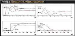
Figure 2 illustrates the difference between aggressive and moderate tuning on setpoint or load change (the scales are identical and the process is a flow loop). If a loop is tuned to respond slowly to a setpoint change, the response will be sluggish for a load change. Different criteria can be used to specify the control objective:
- Fast response and minimizing errors: Examples are the Ziegler and Nichols formulas; the quarter amplitude decay corresponds roughly to this definition.
- Minimizing the area of the error after a setpoint change or a load change: This can be applied to minimize the integral of absolute error, minimize the integral of the error squared, etc.
- Applying a limit to the overshoot after a load change or a setpoint change.
- Reaching the setpoint at the maximum speed without overshoot (critical damping).
The differences between aggressive (top) and moderate (bottom) tuning on a setpoint change (left) or load change (right) for a typical flow loop.
These criteria correspond to a specific control objective, giving the desired performance. For each criterion, formulas exist to tune the loop, or software is used to obtain the tuning parameters.
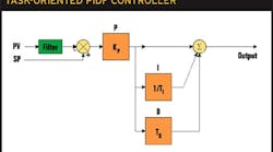
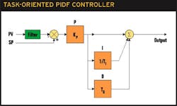
When analyzing the formulas, we observe that the integral time and the derivative time depend mainly on the dead time. The time constant has little or no impact on the controller tuning parameters. This can be explained by the fact that the transient response depends on the dead time.PID ReviewThe proportional-integral-derivative (PID) controller is a well-known algorithm. A PIDF controller includes proportional, integral, derivative, and filter functions:The Proportional (P) part of the PIDF controller is the main part of the algorithm. The output of this part is proportional to the amplitude of the input, usually the error.The Integral (I), also named reset, is used to ensure the process variable will reach the setpoint. The output for this part moves at a speed proportional to the input. The integral time TI corresponds to the time needed by the output to move by the same amount as the input.ts< τPVTDTdTI
It is also possible to establish a relationship between the dead time and the closed-loop response. The natural period t0 is the period for unstable conditions: on/off controller, a proportional-only controller with a high gain. This natural period is the maximum speed at which the loop can move. Using less-aggressive tuning to let the process stabilize and reach the setpoint will produce a damped period longer than the natural period; if the tunings are reduced sufficiently, the damped period will disappear. For all processes, the natural period is always between two and four times the dead time:2td < TO < 4td
tO < tosc
tosc ?? 6td
tosc ?? 2TI
After a setpoint change, a process variable will reach the setpoint after fewer than two or three damped periods. If the cycling is absent, the process variable will reach the setpoint after 10 to 15 times the dead time:tset ?? 12td
tset ?? 6TI
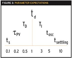
When troubleshooting a control loop, if we know the above relationships, it will be easy to detect abnormalities such as too much integral. Also, just looking at the trends, we can determine if the values make sense. The expected relationships, as shown in Figure 3, are:ts< τPV< TD< td< TI < tosc < tset

Leaders relevant to this article:
