article_291_tnail

Hydraulics provide a versatile solution

Aug. 18, 2005
Controls for hydraulically powered machines provide sophisticated functionality beyond brute-force capability. Field Editor Jason Christopher investigates the implications for today's machine builders.
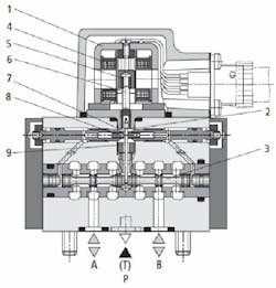
By Jason Christopher, Field EditorSOME PEOPLE will tell you there hasn’t been anything new in world of industrial hydraulics in years. These might be the same people who would contend that there haven’t been advances in the internal combustion engine either. Just as the fundamental principles of the internal combustion engine still apply today, so do the fundamentals of hydraulics. What has changed is the refinement these products have undergone, and the dramatic increases in performance that have been realized.Not Your Father’s Hydraulic System“When I started in this business, hydraulics was an easy discipline,” says Brian Lee, a seasoned veteran in the controls industry now working for Machine Tool Builders Inc., Machesney Park, Ill., a retrofitter and upgrader of machine tools systems. “Forward and back was all it did, and it wasn’t hard to figure out. Nowadays, you have to double check if it’s a hydraulic axis, or an electric servo axis, because you can’t tell them apart by the way they perform.”The fundamentals of the hydraulic valve haven’t changed in more than 40 years, states Mike Panebianco, territory manager for Parker Hydraulics, but what has changed is the technology that controls the valves. “We used to have design centers filled with mechanical engineers to develop our valves,” he recalls. “Now, we have all electrical engineers to develop our new products.”Panebianco refers to the amount of electronic control that now is available for hydraulic applications. The advent of these electronic advances comes on two fronts: in the overall system control, as well as the control of the individual valve.“We’ve given our hydraulic motion controllers the ability to control pressure and force, in addition to controlling position, with the ability to smoothly transition between position and pressure control,” states Peter Nachtwey, president of Delta Computer Systems. “Such capabilities enable hydraulic systems to become more productive and decrease lifecycle costs.”Most engineers are familiar with the “bang-bang” approach that has been used for years, where a directional control valve drives a cylinder to mechanical extremes with little or no regard for finesse. However, with the precision resulting from advances in electronic control of the valves, the performance of a hydraulic system can exceed that of an equivalent servo system for some applications.“The control electronics compensate for the effect of the differential cylinder, linearize flow characteristics and solenoid characteristics of the valves, and raise the damping level of the drive through feedback of status variables,” says Johannes Grobe, head of product management of industrial controls for Rexroth Industrial Hydraulics. “We see applications developing acceleration to 80 g. We have aluminum die-casting machines with electro-hydraulic axes that decelerate from 600 m/min to 0 in 30–40 msec because of the performance that comes from combining the power of hydraulics with the control of electronics.”More Sophisticated BasicsBefore selecting a valve to meet the application requirements, system designers need to know exactly what the application calls for, as well as what they will get when asking for various different valve types. The terms “servo valve” and “proportional valve” are discussed a lot, but it is important to understand the nature of each, as well as their benefits and shortcomings prior to making a selection.Servo valve technology has been around since the 1930s, and received a lot of attention in the 1960s as a means of addressing space and weight issues while trying to get the space program off the ground. With a servo valve (See Figure 1), a linear change in coil current results in a linear change in spool position, as well as a linear oil flow change through the valve. Servo valves are precision components, manufactured to exacting tolerances in order to get the desired performance, especially in flow characteristics. FIGURE 1: THE VENERABLE SERVO VALVE
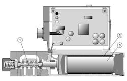
A linear change in a servo valve’s coil current results in a linear change in spool position, as well as a linear oil flow change through the valve. Source: Rexroth Hydraulics Proportional valves (See Figure 2) on the other hand typically are less expensive valves built to less stringent tolerances. Contrary to what you might expect, the proportional valve contains built-in feedback, while the servo valve often times does not. The proportional valve uses feedback on the spool, typically in the form of a linear variable-displacement transducer (LVDT), to measure spool position. The spool position then is fed back into the valve controller, where the controller adjusts accordingly to linearize flow. FIGURE 2: A PROPORTIONAL RESPONSE

The valve spools (1) of these proportional valves are actuated by a moveable coil (2) over a friction-free permanent magnet cylinder (3). This direct actuation of the spool, coupled with high resolution feedback, allows the valves to be positioned more precisely, in less time. The end result is high speed precision. Source: Rexroth Hydraulics

It is important to remember that a linear displacement of the proportional valve spool does not necessarily equate to a linear change in oil flow. The valve amplifier (controller) uses a mathematical function to determine the appropriate spool position for the flow requested by the command input. Despite the built-in feedback, proportional valves typically have lower performance than a servo valve; however they are usually more tolerant of contaminants in the oil.There also are hybrids referred to as servo-proportional valves. These valves incorporate much of the precision of the servo valve with the spool feedback of the proportional valve to create a high-performing device. The most demanding motion-control applications might use servo-quality proportional valves such as these.Magnetostrictive displacement transducers (MDTs) close the loop on high-performance hydraulic motion control systems. MDTs allow the system to very precisely measure the position of a cylinder along the length of travel. An electrical impulse is sent down the shaft of the cylinder, generating an ultrasonic frequency from the interaction between the pulse and a position magnet located on the cylinder. By measuring the response time of the ultrasonic wave, the position of the cylinder can be measured accurately. It is not uncommon to have sensors that can measure position down to ±10 µm.Open Systems
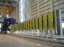
“SSI [Synchronous Serial Interface—ed.] feedback for MDT sensors represents one of the greatest advancements we have seen in recent years for hydraulic system control,” states Bob O’Brien, principal engineer for system integrator Concept Systems, Albany, Ore. “There is no need to rescale after replacing a probe, or to re-home the system at startup. Most importantly, this represents a universal interface for measuring position.”These sentiments are echoed by Nachtwey, who says Delta uses open-system technologies, so it doesn't need to reinvent the wheel. “Delta’s tools run under popular Windows operating systems and Delta controllers interface to standard transducers and standard system buses,” he states.A good example of a big, impressive standards-based hydraulic-power control application comes from Electroimpact, Mukilteo, Wash. The company is the prime contractor for supplying automation tools to the Airbus plant in Broughton, U.K., which assembles the wings of the world’s largest commercial aircraft--the Airbus A380.The huge size of a completed wing panel—up to 111 ft long and weighing 8,818 lb—poses a big material handling problem. “Using cranes to position the panels doesn’t work,” says Electroimpact project engineer Ted Karagias. “The wing panels are distorted when suspended from the cranes.”Electroimpact devised a multi-arm manipulator (See Figure 3) to maintain the panel’s proper form and provide precise positional control while presenting the panel to the wing structure for fastening. The company designed and built an array of six coordinated servo hydraulic arms that engages the panel along its entire length. FIGURE 3: CLIPPED WINGS

A completed AirBus wing panel poses a big material handling problem. Electroimpact devised a multi-arm manipulator to maintain the panel’s proper form and provide precise positional control while being fastened. The machine is an array of six coordinated servo hydraulic arms, and the primary axis of movement is managed by a closed-loop servo hydraulic controller integrated with an SSI linear scale, load cell and servo solenoid valve. Source: Bosch Rexroth

“Basically you have a statically indeterminate system,” says Karagias. “The panels will twist, bend, and kick as they react to the forces introduced by lifting equipment. To overcome this problem, two of the six arms control the vertical position of the panel, while the other four arms act as slaves imparting a constant programmed force upon the wing panel. That way, when the positioning arms are commanded to move either up or down, the load-seeking arms follow along to maintain the panel’s form.”The primary axis of movement is maintained in closed-loop servo control by a Rexroth HNC 100 servo hydraulic controller. The controller integrates an SSI linear scale, load cell, and a servo solenoid valve. This configuration provides fine position control with seamless transition between position and force control.According to Karagias, “The servo axis provides exceptional control over panel position, and the controller imparts important system benefits,” says Karagias. “It simplifies system-level PLC logic and position control instructions. It also allows direct access to all critical system components and provides servo control via the SSI port using analog and digital I/O, ProfiBus and CANbus, regardless of PLC scan rates or network speeds.”By choosing to incorporate open-system standards such as serial encoder interfaces and fieldbus connections into product designs, manufacturers do several things. They create common platforms that allow their customers to incorporate their products more easily. Open system solutions typically are easier to implement into the overall control system scheme than proprietary counterparts. The hydraulic controls might represent only one portion of the overall control system, so the ability for it to interface with the rest of the control system is a must.Further, by migrating to a more open-system approach, the system designer can incorporate products from more than one vendor in the overall solution. Even though one manufacturer might be required for a specific aspect of the project, the engineer has the ability to select the best (or best valued) items for the required application, keeping him in the driver’s seat on the design.Grobe says Rexroth valves “are equipped with interfaces to all commonly-used fieldbus systems such as Profibus, Interbus or CANopen.” Ideally you would want the valves to be located as close to the point of use as possible in order to maximize performance. This might be a distance from the control cabinet, so wiring a valve manifold might present a challenge. Fieldbus-enabled valves facilitate incorporating them into your system. FIGURE 4: PLAYS WELL WITH OTHERS

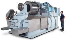
Because of the interconnect ability of modern hydraulic controllers, a hydraulic axis can be integrated into the CNC just as a traditional electric servo axis would be. MJC Engineering & Technology configured a CNC for two-axis, z and rotation control. The hydraulic control module fits directly into a standard electric servo drive bank and matches the physical properties of the other drives, but it also matches the electrical connections including equipment bus and DC link. Since the electrical connections, as well as electrical interface match, the integration of the unit goes much smoother. Source: Siemens

Another good example of standards-based solutions is the way hydraulic work axes are incorporated into seemingly traditional CNC machines. Because of the interconnect ability of modern hydraulic controllers, a hydraulic axis can be integrated into the CNC just as a traditional electric servo axis would be. After developing a massive metal-spinning machine (See Figure 4) for pressure vessels, MJC Engineering & Technology, Huntington Beach, Calif., configured a Siemens Sinumerik 840D CNC for two-axis, z and rotation control. “The rotation axis used a standard hydraulic cylinder with feedback converted from inches to degrees of rotation to simplify the programming,” says MJC’s Dave Grupenhagen. “Both axes are powered by a Siemens HLA Module, while Profibus handles the data interchange between the CNC system, operator panel and PLC.”Even though the HLA is specifically designed for the control of hydraulic axes of motion, it fits directly into a standard electric servo drive bank.  Not only does the module match the physical properties of the other drives, but it also matches the electrical connections including equipment bus and DC link. Since the electrical connections, as well as electrical interface match, the integration of the unit goes much smoother.That’s Not All
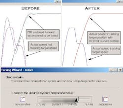
These advances represent significant improvements in hydraulic control, but they still might not be enough to make you think about leaving your current technologies. There are other factors that could sweeten the deal. Software could be one of those factors.Like any electric servo-based system, an axis of hydraulic control needs to be tuned for optimum performance. “Advances in programming and tuning tool technologies allow machine designers and integrators to complete optimized designs much more quickly and for lower development cost than would have been possible in the past,” adds Nachtwey. “A robotic system integrator in Quebec completed an application with our new Tuning Wizard software (See Figure 5). The engineer tuned 10 motion axes in 15 minutes--a feat that would be impossible using standard trial-and-error tactics.”Completion of the system installation does not mean it is the last time you’ll hear about that system either. O’Brien contends that, “to the end user, ease of maintenance represents the biggest advantage that our customers enjoy. Reduction of the maintenance burden on them relates to more uptime and more revenues.” FIGURE 5: TUNING IS A WIZ

Programming and tuning tool technologies let machine designers and integrators complete optimized designs quickly and for lower development costs. A robotic system integrator tuned 10 motion axes in 15 minutes--a feat that would be impossible using standard trial-and-error methods. Source: Delta Computer Systems

Still the WorkhorseDon’t get the wrong impression of industrial hydraulics. The reality of hydraulics being used for high-load, high-force, applications because of its brute strength still is a valid truth. What’s new is the elegance that hydraulics now can possess at the same time.“Fluid power actuators are comparatively small, even for applications that involve heavy loads versus electric motors for the same application,” explains Nachtwey. This is partially because a hydraulic system can be sized for the average load requirements, not the peak load as necessary for electromechanical systems. Hydraulic systems can incorporate accumulators near the load to store energy during peak power requirement times. Conversely, the power unit charges the accumulator during less-demanding portions of the machine cycle. Therefore, the pump only needs to output enough power to meet the cycle’s average requirement, provided the accumulator is sized to handle the peaks. Electric motors, on the other hand, might be better suited to continuous duty applications where the accumulator of a hydraulic system fails to hold any advantage.