article_316_tnail

Better wafer breaking

July 15, 2005
Loomis Industries designs semiconductor wafer dicing machines and has introduced a compact Ethernet switch that helps sustain reliability in fine-tuning scribing and breaking processes.
By Jim Montague, Executive EditorSCRIBING AND breaking semiconductor wafers is a lot like cutting glass—only on a much, much smaller scale. Modernization in the compound semiconductor market usually is associated with fine-tuning scribing and breaking processes. However, as far back as 30 years ago, scribe dicing of wafers yielded irregular quantities because the tools weren’t manufactured properly and/or those tools weren’t accurately positioned in the system. To address these issues, staff at Loomis Industries, St. Helena, Calif., collaborated with its suppliers and customers, shared trial and error, and took risks to develop a scribe alignment and accuracy process, which the company claims is unmatched by its competitors.“Some of our older equipment has been on production lines with very little maintenance for more than a decade,” says Jim Cook, production manager for Loomis. “By using quality, proven components on our new LSD-150 scribe and break system, we hope to continue this level of reliability and productivity.”ALLOYS FOR WAFERS
Loomis’ wafer building process consists of dicing wafers made of gallium arsenide, indium phosphide, and other semiconductor compounds less than 300 µm thick. Wafers are covered with thousands of copies of a device that a manufacturer wants to assemble. These copies of the chip are separated from each other via Loomis’ scribe-and-break system. The devices are laid out on the wafer in a grid. The space between the devices is referred to as a “street.” Streets are typically 50 µm wide and act as the pathway for the scribing process.ETHERNET AIDS MOTION CONTROL
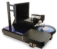
In its most recent quality improvement effort, Loomis decided to use Galil Motion Control’s motion and I/O components as the core of its new LSD-150 scribe-and-break system (See Figure 1 below). Galil’s motion controller, a two-layer module containing the motion controller and the amplifier, and its I/O board provided two communication options: serial or Ethernet. “Ethernet was the ‘cleaner’ solution,” explains Cook. “Many PCs sold today aren’t designed with serial ports. They often come with only USB, but most PCs have Ethernet built-in.”FIGURE 1: HIGH WAFER YIELD

Loomis Industries reports its LSD-150 scribe dicing machine is bringing about a new standard in yield, throughput, and cost-effectiveness by achieving +99.5% yields and industry-leading throughput times in 24/7 production environments.

Loomis next had to find a manufacturer of industrial-grade, small-footprint Ethernet components. “A switch was preferred over a hub,” says Cook. “Our programmers said a switch is more efficient in this application.” However, Galil’s hardware wasn’t designed to be daisy-chained, so an Ethernet switch was needed to link the Ethernet devices that occupied the limited space in Loomis’ new LSD-150 chassis. “I was looking for a product aimed at giving its users compact size and versatility in power connection,” adds Cook. He found a Contemporary Controls switch with roots in the building automation sector fit his needs quite well. “The BAS switch was a perfect fit because it didn’t use a power transformer that had a proprietary plug on the switch housing,” adds Cook.In addition, Loomis already had a 24 VDC switching power supply inside its LSD-150 machine. “With this Ethernet switch we were able to use up to 36 VDC with simple screw plugs to easily connect power from our switching power supply,” he says.The BAS switch size also was a factor in Loomis decision to use it. “As small as possible, that’s what we needed,” adds Cook. “When we decided to use the Galil system, we were short on space. The Galil components are much larger than what we had used. A switch designed for home or office wasn’t an option.”Measuring 3.3x0.9x3.5 in., the DIN-rail mount switch provides five 10/100 Mbps shielded RJ-45 ports. Each port opts for the auto-negotiation protocol to select data rate, duplex and flow control. All five ports are Auto-MDIX compliant, so any port can operate as an uplink port to another switch, eliminating the need for crossover cables. It also offers low-voltage, wide-range AC or DC power sources, as well as LEDs for activity/link, data rate and power indication. Built-in broadcast storm control prevents excessive broadcasts from degrading network performance.NETWORKING THE MACHINE
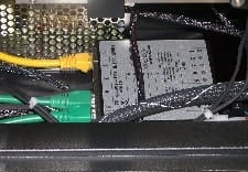
Loomis says it took much time and effort to make certain an Ethernet-based network and infrastructure was correct for its scribe-and-break process. The system includes a PC and the LSD-150 unit, which is used inside environmentally controlled clean rooms.This PC is positioned near the LSD-150 because interaction sometimes is required from the operator via the mouse and the keyboard. A typical, 2-m, unshielded (UTP) CAT5 Ethernet cable connects the PC to the LSD-150. The PC functions as the supervisory controller. All the motors, digital I/O, and analog I/O are controlled and monitored by the Galil components to do the real-time servoing. These components interface with the PC through the BAS switch (See Figure 2 below). Meanwhile, an I/O controller eliminates the need for an external PLC. It includes a 32-bit microcomputer with memory and multitasking for programming various I/O events.FIGURE 2: SERVO, CONTROL INTERFACING

All of the LSD-150 machine’s motors, digital I/O and analog I/O for its scribing and dicing process are controlled and monitored by Galil’s components to do real-time servoing, and are interfaced with the unit’s supervisory controller PC through its Ethernet switch.

The engineers at Loomis say it was an obvious choice to use open architecture to build in modularity for future expansion. ”Occasionally, we’ll customize the machinery to meet our customers’ requirements,” Cook says. “We can install extra modular controllers under the supervisory PC controller, if we chose to add more motors or other devices.”Through the user interface, the PC tells the LSD-150 how to process the wafer once it’s loaded on the scriber. The PC and the corresponding recipe file dictate scribing air pressure, breaking air pressure (both analog controls), scribing and break speeds, and focus positions.Cook says Loomis’ programmer reports that, “Ethernet communications are not time-critical, but there’s a strong likelihood that any delay more than 1 ms per message will begin to affect throughput.” He explains that scribing and breaking throughput depends on many factors, such as the die size, the material being scribed, scribe speed, break speed, the size of the wafer (the machine can handle 2-6 in. substrates), the shape of the wafer, and the process, which might be done entirely on the LSD-150 or also involve another Loomis machine.Cook feels that the LSD-150 machine outperforms all competition in scribe-dicing wafers. Besides its PC, LSD-150 incorporates other structural elements in its design. These includes a computer monitor, two motor and lead screw-driven air slides (x and y-axis), and one auto-focusing video microscope controlled by one DC servo. The other DC servo drives the turntable for the theta axis. The theta stage is mounted to the x-axis slide, which is responsible for indexing the wafer, street-by-street, under the scribing assembly. The three-phase motors control the scribe-axis (y) and the die-index axis (x). The scribe, break, ring clamps, and mandrel mechanisms are pneumatically actuated. This process also allows for various digital and analog inputs and outputs, including air pressure regulators to control the scribe and break forces. The Sidebar explains the process steps involved.After network-enabling its Galil-based system via Ethernet, Loomis reports its new scribing and breaking machine was able to do complete production runs without interruptions. “Ethernet is a time-tested technology that has great capability for problem diagnosis and resolution,” explains Cook. “Other reasons for Ethernet’s popularity in this application are its speed, flexibility in expanding generic devices, that it doesn’t need special cables or connectors, and that Ethernet components are inexpensive and available worldwide.”

Dicing in the Streets

THE LOOMIS LSD-150 process begins by mounting the wafer on dicing film that is secured with holding rings. The ring-film-wafer assembly is placed onto the LSD-150 theta stage. Once the ring assembly is clamped down, a support mandrel swings (pneumatically) into position underneath the wafer and film. Next the x-axis moves the wafer to the center position.

Next, the y-axis moves the microscope over the wafer’s center point, focusing on its surface. The pattern recognition (PR) system begins looking for the patterns programmed for that specific wafer’s orientation. All the process information is stored in the wafer’s recipe file; including the patterns used by the PR system, scribe speed, scribe and break forces, etc.

“With the aid of the PR system, the LSD-150 system rotates the theta axis,” says Cook. “It continues with minute rotation adjustments and PR checks until the motion of the y-axis, (scribe-axis, microscope holder, and break wheel holder) is parallel to the streets to be scribed in this direction on the wafer.” He adds the x-axis moves the wafer to one side and then indexes back until the first street at the wafer’s edge is recognized by the PR system. The PR system verifies that the street is centered under the targeting reticule and the processing begins. Next, the y-axis will move out over the far edge of the wafer, drop the scribe tool into the scribe position, and then the y-axis will retract at a predetermined speed. “The diamond scribe tool will be pulled across the material, down the middle of the street, creating a crack underneath the visible line made by the scribe tool,” he explains. “When the wafer is broken, it will break along this line.”

Finally, at the end of the scribe stroke, the scribe tool will lift into its non-contact position. Now, the x-axis indexes to the next street. The PR system checks position again, and then the motion repeats. After several streets, if the PR system fails to detect any indexing errors, it will automatically program an on-the-fly pattern, so that positioning can be monitored without stopping the camera over the wafer. Once the first pass is completed, the wafer will be automatically rotated 90 degrees by the theta axis. The x-axis will re-center the wafer, the theta axis will align, and the next pass will start, as before, until processing is complete.