INDUSTRY EXPERTS sometimes argue these days about what makes a vision system a vision system. Vision devices come in self-contained packages, a.k.a. the vision sensor, or as a modular system known typically as machine vision that consists of computer, lighting and optics, camera or sensor, image-acquiring frame grabber, and application software.
Whether you use a vision sensor or machine vision system, either one is likely to be 20% cheaper then it was 10 years ago and many times more powerful. Thanks to accumulated libraries and rapid application development (RAD) tools, analysis functions that were hand coded in the past now can be selected as a feature or an object that can applied to the vision-processing task.
Which ever is the case, manufacturers, system integrators and, more recently, machine builders have been building vision into industrial machines quite successfully for a while now.
We’ve become familiar with the usual applications in robot guidance, pick-and-place, and inspection/rejection, but there are some interesting applications that use vision to help control the process and keep it from turning out products that flunk the final vision-based inspection process. Examples of these applications are all over the map—from cutting meat, producing semiconductors, picking and analyzing leaves in crops, guiding surgical instruments, and others. We’ll consider several of them.
Sensor or System?
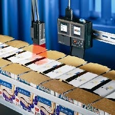
Vision sensors typically are self-contained devices with built-in charge-coupled device (CCD), processor, software, and communications in the same box. Smarter than photoelectric and laser sensors but not as capable as a PC-based machine vision system, vision sensors offer a lot of functionality in a price range of about $1,000-8,000 (See Figure 1).
This self-suffcient vision sensor has speeds of four, six, or 12 ms, and has an intelligent lighting and adjustable focus. Advanced algorithms provide for wide viewing area, enhanced pattern recognition, brightness, character detection, label position, target width, etc. Source: Omron
The choice of vision sensor or machine vision system often is a matter of degree and common sense. What speeds are needed and what special needs does an application require? Is vision being used for inspection or for control? “High-speed color, custom-lighting, specialty vision systems are available for press color registration,” says Jeff Schmitz, corporate business manager for Banner Engineering Vision Products. “These sensors perform far better for high-speed printing press color registration than any vision sensor today.”
Vision sensors fill a niche between photosensors and machine vision systems. While color-mark photoelectric sensors have been one solution for checking registration marks (pass-fail) for small packets such as sugar or cream used in a restaurant, vision sensors add quality optics and often are capable of speeds of 30-500 frames of video per second. Though usually not considered for printing press register applications, vision sensors, according to Schmitz, can perform decent binary large object (BLOB) and intensity or average gray-scale algorithms that can calculate the amount of darker features on a tobacco leaf.
“Typically a machine vision system has greater configurability and can handle a broad range of applications, often using generic functions,” adds Zuech. “A PC-based machine vision system can be effective for some applications with just cameras, FireWire inputs, and software. But for high-performance applications, frame-grabber boards serve as buffers and offload processing from the PC’s CPU.”
The key differentiator between a machine vision system and a vision sensor seems to be the machine vision system’s ability to combine several applications or functions, e.g., find, OCR, 2D symbol reading, presence, pattern recognition, etc. While Schmitz thinks of a vision sensor as a Swiss Army knife capable of fitting into several applications, Zuech feels that typically a vision sensor either will work or not work in an application, but a vision system can usually be engineered to work in most any application.
Vision sensors are not necessarily thought of as feedback devices for closed-loop control; rather they often play roles in pass-fail inspection systems. But technology advances slowly are pushing them beyond pattern recognition roles and into limited forms of control. While some vision sensors look for specific patterns or marks, improvements in vision sensor technology (intelligence, processing power, sensor elements) allow them to work with any unique pattern on a part, thus adapting to new registration marks.
According to John Keating, product marketing manager for Checker presence sensors from Cognex, today’s vision sensors can see the actual image the device sees. Unlike photosensors, vision sensors perform algorithms to find parts without fixturing, and also are good at finding registration marks. Keating claims today’s high-performance vision sensors also can be used for registration or web-cutting/perforating/printing applications. In fact, says Brian VanderPryt, vision system specialist at system integrator Indicon Corp., Sterling Heights, Mich., when combined with the proper integration and system design, vision sensors can be used successfully for feedback in a closed-loop control system.
Software Simplifies Configuration
In earlier days, vision software was mostly a roll-your-own proposition. Developers had to calibrate the camera, lens, and lighting systems; manage a database of test images; develop a vision algorithm prototype; develop an operator interface; and document the vision algorithm. There were few libraries available, and most functions had to be hand coded, often in C, and later on in C++. With C++ and other object-oriented systems, commonly used functions became stored in modules for relatively easy reuse.
Today, says Adil Shafi, president of Shafi Inc., a Brighton, Mich.-based group that specializes in vision guided robotic software integration, users can customize applications and this applies to products, processes, solution type, language, process-specific help text, vision tools, communication protocols, interface buttons, filtering of features and geometric zones.
While libraries save vision system developers a lot of time compared to programming lines of C code, the use of rapid application development tools goes a giant step further. According to a National Instruments white paper, Rapid Application Development for Machine Vision—A New Approach, substantial reductions in development cycles are possible. For an application that took 178 hours to develop using vision libraries, the paper claims that same application took 42 hours using RAD tools. For a third-party developer that charges $100/hour, the cost savings can exceed $15,000. Further, development of a gauging strategy using vision libraries can take 40 of those 178 hours; with RAD tools, this time can be cut to six hours. Integrating vision software with image acquisition and other I/O is another big time consumer, requiring up to 30 hours in this same application. With the RAD approach, time can be cut back to 16 hours.
To Be 2D or 3D
When vision systems were more expensive, system designers would think of ways to perform 3D vision with single cameras to hold the costs down. “In general, you can do single-camera 3D for any application,” notes Shafi, “but it’s necessary to make sure the features are repeatable. For example, finely machined metal blocks will have repeatable features, but stamped metal sheets or plastic trays will not have repeatable features.” Determining whether a specific application needs 3D is not necessarily quick and easy.
According to Robert Lee, strategic marketing manager at Omron Electronics, when two cameras perform 3D, the cameras usually are simulating human stereoscopic vision, and it is more likely that the application is either a depth or perspective application where the varying distance between the camera and object is constantly being determined. Lee contends that this type of application can not be done effectively with one camera.
| "A PC-based machine vision system can be effective for some applications with just cameras, FireWire inputs, and software. But for high-performance applications, frame grabber boards serve as buffers and offload processing from the PC’s CPU.” |
In another application, Indicon used end-of-arm, tool-mounted cameras to unload a pallet of bins. The bins were stacked 3x3, four rows high, and never in an exact position. The robot would move to a picture position above the pickup, and use the camera data to fine tune the pickup position. “We’ve used cameras to provide a deflashing robot with the exact position of pockets in an engine block that needed to be machined,” adds VanderPryt. “The cameras were needed to account for differences of +/-0.13 mm in the casting process.”
VanderPryt suggests that 3D also is practical for gauging operations. Cameras can be calibrated using materials that are not temperature sensitive (carbon fiber, for example) and can compensate for changes in temperature.
Vision Does Feedback
One established machine vision application is maintaining color registration in a color offset printing press. To close the loop, the vision system first has to detect defective output before it can correct it. Zuech says machine vision-based registration control in printing systems can reduce print waste by 20-40%. But for operators to take advantage of these technologies, presses often need retrofits, and with some presses there is precious little room for additional hardware.
Vision as a control element is limited only by the imagination, and the potential cost savings it can represent. FMC FoodTech uses a rather elegant 3D vision system (except for the cameras, it’s completely designed and built in-house) in its aptly named DSI Accura Portinoner. If you’ve ever noticed how consistent the size of your fast-food, grilled-chicken sandwich is, or how the breaded chicken pieces seem exactly the same, this is no mystery. “This machine takes in boneless poultry breasts, scans them for density and color with multiple cameras, analyzes the mass and configuration of each, and determines how to cut it into the maximum number of pieces with the least waste,” says Jon Hocker, DSI product manager.
The color camera in the machine performs feature recognition—such as locating the fat on the piece—and also uses this information to determine cutting trajectories. The machine’s high-pressure (50,000-60,000 psi) water jets—each smaller than the diameter of human hair—to do the cutting, and the cutting path, which can be anything that the operator desires or can sketch, is determined by the data processed from the vision system. “In essence, the machine cuts each piece after deciding how to make the most money on it,” notes Hocker. “Sandwich-size pieces are cut with an accuracy better than three grams. The belt runs at 60 ft/min, moving 1,500-3,000 lb per hour.”
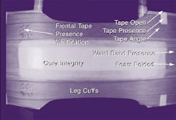
Another real-world application is AccuSentry’s Series 9000-D diaper inspection system from AccuSentry, which according to the company’s owner, J.J. Roberts, consists of a machine vision system that reads imprinted registration marks to maintain control of the process. The absorbent disposables production line (See Figure 2) is a high-speed, PLC-based manufacturing environment with many raw material variables to consider, in addition to the final integrity of all the components and their position. With this feature, information the inspection system gets from the product can be used to supply feedback and implement control functionality on a production line at rates to 700 disposables per minute.FIGURE 2: NO QUALITY LEAKSMatt Quinn, partner at Epic Vision Solutions, St. Louis, an integrator that works with most of the major machine vision suppliers, likes to talk of a “moderately complex application” used in a bottling line to locate and position a plastic label on a bottle without mechanical cams and physical location molds. The system used two Cognex Insight 5400s with PatMax software, Perkin Elmer Xeon X-Strobe lighting, a ControlLogix PLC, EtherNet/IP and CANbus. Camera 1 pre-oriented the bottle for final inspection by Camera 2. The cameras were triggered from a master machine encoder. The camera acquires and processes the image to give a bottle position and turning-offset value for the individual bottle servo tables to turn. A microcontroller reads the turning offset values from the cameras and sends a servo drive command to turn the bottle prior to the first labeler aggregate. The vision system does 100% bottle inspection for orientation at very-high speeds. The vision system, which was designed for retrofits as well as for newly-built labelers, provides a feedback solution capable of orienting the position of the plastic label on a bottle with an accuracy of less than 1/16 in.

Leaders relevant to this article:
