If they’re not careful, this pressure to be all things to all customers can push builders into costly custom solutions. These can force them to spend too much time and money simply building, and have too little time remaining to improve machine designs and performance, and help customers achieve their long-range plans.
Automatic Feed Co. (AFCO), Napoleon, Ohio, a privately owned designer and manufacturer of coil-handling and press-feeding automation equipment for automakers and their Tier One suppliers, saw these events converging many years ago. The company strove to take a standardized approach to its machine building, but saw the realization of those plans resisted by market conditions of the time.
By 2003, AFCO had extensively researched its customers’ needs, and saw a tremendous opportunity to improve both its customers’ and its own bottom lines with a standardization program that made its machines lean, flexible, and productive. The company called this process its Standardization and Modularization Action Resource Team (SMART) initiative. Consequently, late in 2005, AFCO launched machines that embody what it calls its “device-neutral, distributed-device architecture” (DDA) approach.
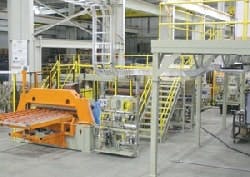
The first system Automatic Feed Co. tackes with its SMART process was a progressive die-stamping line for an automotive OEM. It consisted of nine electrical modules/machines requiring approximately 3,000 sq. ft. of floor space and hundreds of automotive components.
What It Takes
The first system Automatic Feed tackled with its new SMART process was a progressive, die-stamping line for an automotive OEM (See Figure 1). It consisted of nine electrical modules/machines requiring approximately 3,000 sq. ft. of floor space. A system this size easily can involve hundreds of components that each OEM might specify from its own favored brands. For an industrial OEM, this can be like re-inventing the wheel for each system it builds.
“Prior to this undertaking, we were driven simultaneously toward cost reductions, ease of use, flexibility, and quality improvement without the comfort of solid, standard machine configurations,” says Kim Beck, AFCO’s president. “Each automaker traditionally has its own set of machine standards, as well as a list of approved component suppliers. We had to study all the various system requirements, and come up with one component-neutral standard that would satisfy each of them.”
Once this was accomplished, says Beck, the company set the design parameters, and called on each component supplier to fit into these requirements. “We wanted a standard plug-and-play concept,” he adds. “It wouldn’t matter whose motors, drives, or valves we used. They all had to fit the system as we designed it.”
Plan Comes Together
Every aspect of AFCO’s equipment design is segmented into standardized subsystems. For the initial progressive die project, this included coil cart, uncoiler, peeler and hold-down unit, pinch roll and crop shear unit, leveler, feeder, exit feeder and scrap chopper, main operator console and main enclosure. These SMART systems are designed with self-contained modular mechanics, control devices, and logic.
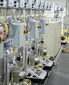
Controls and hardware devices are located on the DDA Stand alongside the machine, reducing the number of enclosures. Since all units are standardized control-neutral subsystems, the stands function as modular plug-and play-devices.
“We locate the industrial controls and hardware devices on our DDA Stand alongside the machine (See Figure 2), reducing the number of enclosures,” says Brad West, AFCO’s senior electrical project engineer. “Since all the units are standardized, control-neutral subsystems, the DDA stands function as modular plug-and play-devices.” This simplification reduces material and labor cost, as well as improving reliability by reducing potential failure points, and easing troubleshooting by concentrating the controls’ location.
“Previously, we’d produce an entire line control that was incapable of being separated. It was an all-or-nothing approach to running the line,” says West. “Now we use multiple programs to run various areas of the line, allowing for independent testing.”
Likewise, using modular I/O blocks, safety blocks, and corresponding cord-and-connector sets helped make modularity the key to simplicity and reliability in installation, commissioning, and reliable operation.
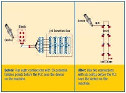
“Take the effect this approach has on one machine switch,” says Tim Barry, AFCO’s senior controls engineer, “and then multiply that effect across the entire machine. We had eight connections and 19 potential failure points from the switch to the PLC, and this was before it even saw the device. Now we have two connections with six points—the switch, connector cord, and the DDA’s machine-mounted network block—before the PLC and the switch communicate (See Figure 3 below). To do this, we implemented a device-level network, in this case DeviceNet, for machine I/O. The HMI and line supervisor communicated via Ethernet.
FIGURE 3: BETTER OFF LESS CONNECTEDNumbers Tell the Story
Based on an actual comparison of two mechanically identical lines, the gains made by the DDA solution were game changing. Junction boxes distributed throughout the line were reduced by 97%. Hardwired terminal points were reduced by 87%. And potential failure points in the control system were reduced 68% (See Table below for more gains).
“Our DDA-based machine lines now are field-wired a minimum of 50% faster, and communication is established 86% faster than with traditional control architectures,” says Barry.
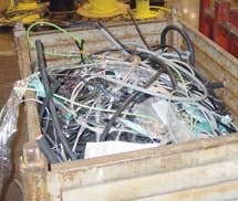
Scrap during installation is all but eliminated since all connections are plug-in. This is typical of the wire and cable scrap generated before DDA.
In addition, scrap during installation also is reduced dramatically (See Figure 4), since all connections are plug-ins.
“The key to DDA is simplicity,” adds Beck. “This applies to all the components, not just the control system wiring implications. A partial list of our DDA-compatible components includes seven communication protocols, six PLC brands, seven drive brands, 11 device brands, and nine compatible robot brands.”
Also, total parts per pinch-roll subassembly dropped 22%, from 492 parts to 386. “The unique parts per pinch-roll assembly were reduced by 34%, from 99 to 65,” says Beck, “It now requires three steps to remove a pinch-roll sub-assembly, but it used to take 11 steps.”
All these gains have resulted in what Automatic Feed calls its “one-day build” cycle. “Since our DDA standard is based on field-proven, integrated architecture, we employ a rapid, modular testing protocol that focuses on individual units,” explains West. “The protocol consists of setting the machinery in place, plugging in the electrical components, connecting to a surrogate PLC, running the machine subsystem in automatic, and certifying the electrical, pneumatic, and hydraulic functional performance.”
Not Done Yet
Despite its achievements, the company believes DDA still has a ways to go before reaching the end of its benefits for itself and its customers. The firm expects further reductions in every applicable category.
While noting the improvements (demonstrated in the Table below), Barry adds Automatic Feed plans to reduce cabling used by another one-third to 2,000 ft. “In addition, we think we can cut those 466 hardwired points we still have by half, and that should mean we’ll cut in-house wiring time from 900 hours to about 450,” he says. Barry also aims to achieve another 15% (about $25,000) reduction in component costs. He also plans to in-house initial communications time down to 1 hour, which is a further 80% reduction, and quite an achievement, considering the 72 hours required pre-DDA.
Table: Gains Achieved Using Distributed Device Architecture
|
Area of Improvement |
Reductions Achieved |
|
Junction boxes |
Down 97%, from 30 to 1 |
|
Feet of cable (communication and power) |
Down 70%, from 10,000 to 3,000 |
|
Machine hard-wire terminal points |
Down 87%, from 348 to 45 |
|
Panel hard-wire termination points |
Down 38%, from 750 to 466 |
|
In-house, initial network communications time in hours |
Down 93%, from 72 to 5 |
|
In-field, initial network communications time in hours |
Down 86%, from 8 to 1 |
|
Number of control enclosures |
Down 16%, from 6-door/241 inches to 5-door/202 |
|
In-house, wire time in man hours per line |
Down 50%, from 1,800 to 900 |
|
Electrical control hardware component costs |
Down 25%, from approx $200K to $150K |
|
Potential failure points* (switch) |
Down 68%, from 19 to 6 |
* Example accounts for single switch; true reduction would account for sum of all devices, which would be greater.
Because Automatic Feed hit or surpassed its original target reductions from concept to customer buy-off in only six months, the company is confident it can get even better results in future efforts. AFCO makes it clear that close customer involvement was key to the success of this project.
“Our customer really bought into the idea, adding their own feedback along the way, which helped things move along,” says West. “As an indicator of their trust in us, they approved 21 deviations from their original spec to push forward this new design. They knew this was moving in the right direction for everybody.
“Since the initial concept, we’ve shipped eight systems to other customers. Additionally, our original customer has ordered seven more SMART/DDA systems. They like this approach so well, that they’ve also adopted it on high-speed blanking and cut-to-length lines.”

Leaders relevant to this article:
