VARIOUS FORMS of machine simulation have been around our industry for sometime now. Many of them started on early Unix platforms in academia, and were aimed more towards simulating early robot designs. In the past 10 years, machine simulation used to predict sequences and events during production has made dramatic advances. As more successes in time-reduced machine commissioning come from early simulation activities, more in-depth 3-D packages are evolving that could lead to complete process simulation and commissioning before installation.
New Machine Development
Assembleon Netherlands B.V., a 100% subsidiary of Royal Philips Electronics, recently implemented simulation tools as part of its new machine development strategy. The project had to meet stringent objectives to be successful These objectives included low-cost hardware, robot-to-robot calibration, robot deformation, printed circuit board (PCB) calibration, diagnostics, short development cycle, urgent deadlines, and exceptional cycle time (see "Design Requirements" sidebar below).
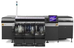
Rik van der Burg, Assembleons motion architect/team leader for motion control and machine dynamics in its mechatronics engineering division, provides some insight into its A-Series SMT machine development, which is made up of three models: AX-30, AX-501 and AX-201 (See Figure 1 below). Parallel placement technology allows production volume flexibility and throughput via robot expansion, says van der Burg. This assures an attractive investment pattern in comparison with all other multifunctional machines, which only can be expanded on a per machine basis. Simple scalability is based on a minimum configuration offering an IPC 9850 output of 30,000 chips per hour (cph) and expandable to 110,000 cph in cost-effective 5.5K cph increments on the same machine footprint.
FIGURE 1: SERIOUS SMT
In parallel to software development for its AX-301 Pick-and-Place machines, Assembelon used simulation software and associated tools to focus on building machines instead of debugging complex mathematics and correction software.
Brian Rubow, Cimetrix product manager, adds that, During initial development, Cimulation played a key role in increasing software development productivity, and in preparing the equipment software for the hardware when it became available, which significantly improved hardware and software development cycles.
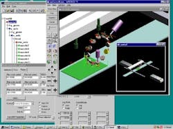
More than one technology supplier to machine builders started with a simulation package as its initial product offering. Cimetrix was created based on research in robotic arm simulation in the 1980s at Brigham Young University. Now the Cimulation package embedded in Code 6 offers significant possibilities to machine builders that want to ensure automation success before starting machine construction. Over the past several years, says Rubow, Code 6 has evolved into a machine control developmental platform that implements Cimulation to predict very sophisticated and precise motion capabilities prior to machine assembly (See Figure 2 below).
FIGURE 2: PREDICT PERFORMANCE, THEN ASSEMBLEThe final AX machines incorporate robots that have their own PC-based control system running autonomously, and include a Code server. Each has on-board calibration maps, which stay with the robot when moving or adding a robot to the machine. The calibration maps are loaded at power-up into the Code package. This allows calibration-free reconfiguration.
All placement heads also have onboard calibration data. Exchanging the placement heads can be done without an accuracy penalty, just as with the robots. Each placement head contains a downward-looking camera for fiducial identification and a laser alignment camera for component alignment. The module is calibrated offline. The short geometrical chainmeasured fiducial information is coupled to the measured component positionresults in the highest accuracy (50 µm accuracy or better at 4σ) achievable, according to van der Burg.
Multiple robots are placing chips on the same PCB, he adds. Geometrical data between the robots is shared to optimize machine output. Robot-to-robot geometrical relations are loaded into the work cell robot models as needed. This is the only on-line machine calibration required.
Simulation, Emulation for Material Handling
HK Systems, a Milwaukee-based automated material handling and supply chain software solutions provider, implements both hardware simulation and control system emulation during the integrated system development phase.
The company uses simulation to determine the base solution to meet the customers requirements. The emulation portion of the testing typically is tied to a meeting with the customer for a demo. The customer gets to see what the final system looks like and can work with the dialogs and screens. This is the time to make any system changes prior to deployment in the field. Since changes during field installation are very costly in a lot of ways, this has big implications for both HK and its customer. Emulation also is the time when stress testing can be done by generating fault conditions and observing the recovery, plus it lets HK engineers push the system beyond design specifications to see where bottlenecks show up.
HK started using machine modeling in the late 1980s. It started with switch and light panels, and eventually evolved into a PC-based software approach.
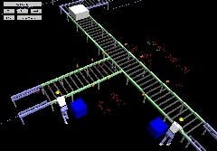
Simulation is used before starting the detailed engineering and eventual system solution implementation, says Curtis Doane, HKs integrated systems controls manager. The simulation model allows us and our customers to evaluate throughput, define system layout, and select various types of equipment (See Figure 3 below). Simulation also is used to evaluate what-if scenarios. This process eliminates costly rework and excess equipment.
|
View a video clip of HKs simulation detail |
The initial package HK implemented was a DOS-based product from now-defunct HEI Co. Recently, HKs simulation solution, now based largely on developing models using AutoMod from Brooks Automation, added RSTestStand from Rockwell Automation as its primary simulation package.
FIGURE 3: SEE IT WORK,
THEN BUILD IT
HK Systems uses simulation before starting the detailed engineering and eventual system solution implementation. The simulation model allows HK and its customers to evaluate throughput, define system layout and select various types of equipment. Simulation also is used to evaluate what-if scenarios.
HK uses various emulation tools depending on the size of the system and the type of control equipment to be emulated. One method HK uses is to add I/O and machine-mounted devices to the simulation model.
HK Systems has been a strong supporter of both simulation and emulation for many years, states Doane. Weve seen tremendous benefits in the use of these technologies for our customers, besides providing the best possible material handling solution.
Generally, AutoMod is implemented as an extension of the simulation model, particularly on large systems such as pallet conveyor systems. RSTestStand is used for new and retrofitted storage retrieval systems and smaller conveyor systems.
The technique of adding control emulation to the actual machine simulation can provide tremendous customer benefits that include:
- Less disruption of production during installation
- Reduced control costs
- Reduced damage to equipment and product
- Fully debugged software before deployment
- Performance objectives benchmarked prior to delivery
Simulation in Product Development
Visual Solutions Inc. provides modeling and simulation for control, communications and signal processing with its VisSim for Mathcad package. No programming is required with VisSim because it uses an intuitive drag-and-drop, block-diagram interface coupled with a powerful simulation engine. Users can select from more than 200 pre-configured blocks, and connect them using point-and-click commands. The simulation engine is time-domain-based, and provides fast and accurate solutions for linear, nonlinear, continuous time, discrete time, time varying and hybrid systems designs. The array of capabilities lends itself to efficient modeling of new products, so the final design and implementation in production merely are next steps in a simulated model-to-production process, says Jim Webb, Visual Solutions sales manager. VisSim has proven to be a valuable tool, especially for product designers.
Wavecrest Laboratories, a design firm based in Dulles, Va., recently completed a time-constrained project with VisSims software. We were given 12 months to develop an integrated interior permanent magnet motor and drive system for a mining pump application, says Guohui Yuan, Wavecrests senior controls engineer. This was an extremely tall order, considering we had to prove the PM motor and variable-speed control technologies to an entirely different industry. The motor and drive hardware components had long design cycles.
Rather than wait for the hardware prototypes to be available, Wavecrest had to start developing the embedded controller software in parallel. Fortunately, we found the VisSim/ECD rapid prototyping tool for Texas Instruments 2000 DSPs, says Yuan. We ran our entire embedded software design cycle in the VisSim environmentfrom system modeling to real-time hardware-in-the-loop simulation, and from design validation testing of prototypes to production quality software release. VisSim block-sets such as fixed-point, TI DMC library, PWM, QEP, CAN, SPI, SCI, and analog/digital I/O were everything we needed for developing motor controller software. Other functions, such as code generation, flash programming, and JTAG debugging, made the formidable tasks of embedded software programming easier. The intuitive graphic user interface allowed more effective communication between software and hardware engineers, adds Yuan.
Machine Tool Part Simulation
Several machine tool builders incorporate some form of simulation in their machine controls to simplify machine setup, and even to simulate the finished part. One of our value-added features is the provision of CNC-resident, interactive shop-level programming software, says Dave Platts, engineering vice president at Hurco Companies in Indianapolis. Within the software, we provide a part-verification function aimed at reducing programming errors, while maintaining ease of use. Hurcos software simulates actual part paths and surface finish through 3-D graphical rendering. Mistakes are identified quickly and easily as a result, adds Platts.
The key user benefits of our simulation approach are reduction in the number of machine sequence/tool selection/data entry errors and the reduction in the time required to achieve a proven part program, says Platts. There are safety benefits, as well, including minimizing chances for part gouging and/or tool breakage. Ultimately, these benefits translate to higher profits on any given machining job.
Hurco claims setup times can be reduced by 50% or more compared with traditional point-to-point, G-code programming, and machine setup techniques. Scrap typically is reduced to one prototype part, but the company says the first part often cut meets specifications.
Another machine tool company, Index Corp. in Nobelsville, Ind., recently added a virtual machine function to its machine control package, and says the new function will allow job shops to simulate machine motions and other functions. Moreover, the virtual software will help operators ensure machining processes proceed as programmed.
Index turning centers, turning mill centers and multi-spindle machines operate from a PC-based CNC control with the virtual simulation package embedded within. This allows virtual machine simulation that maps actual machine configuration data, allowing set-up verification before commencing machining operations.
Whats Next?
Research continues on how to optimize process and machine operations to create efficiencies never before achieved. Techische Universiteit in Eindhoven, Netherlands, is researching a model to develop quantitative methods for designing supervisory controls for machines. The research focuses on integrating performance analysis with system verification based on models of supervisory machine controllers (SMC), and model-based integration and testing.
Other research on processes includes CIMP, Cornell Universitys Injection Molding Program. CIMP released its own system for optimization and process control, called Integrated Molding System (IMS), funded by C-Mold, Moog Japan Ltd., United Technologies Automotive, GINTICSingapores Institute of Manufacturing Technology, and the National Science Foundation.
IMSs patent-pending, adaptive control method is based on measuring mold separation throughout the molding cycle, then modeling that information to adapt to future molding cycles, creating a never-ending filtering process for optimization. IMS uses simulation software to determine machine set-up conditions based on user-entered part design and quality requirements. The software simulates results to derive the recommended machine setup conditions. The variables simulated include cooling time, temperature profiles, ram velocity and injection and holding pressures.
Besides this type of research to extend machine life cycles, and subsequently product life cycles, suppliers of 3-D computer-aided engineering software that is coupled with robust simulation software are engineering a revolution in machine simulation. This evolving development has gained attention from major machine control suppliers. Siemens AG, for one, has signed partnerships with Dassault Systems for its Delmia V5 Automation Platform, and product life cycle management software developer UGS.
Patrick Michel, vice president, Delmia Solutions, claims the new Delmia V5 package is functioning at several beta sites, and will be monitored prior to official launch. This package includes a smart device builder, 3-D CAD modeling of most all electromechanical components used in a machine environment, a PLC programming environment and control systems simulator, which verifies machine performance before deployment.
These new developments open the door to the eventual virtual process/machine where all attributes can be simulated and/or emulated prior to construction and deployment. If thats the case, the virtual factory is not far off.
Design Requirements
Assembleon, a division of Philips NV in the Netherlands, defined these machine design needs that were aided by simulation software:
- Robot-to-robot calibrationto synchronize multiple, multi-axes mechanisms located in close proximity, and operating simultaneously requires high-accuracy calibration between the mechanisms.
- Robot deformationmulti-axis Cartesian mechanisms are subject to several degrees of deformation.
- PCB calibrationto place components onto a printed circuit board, the precise position and orientation of the board must be measured and taken into direct consideration during placement.
- Diagnosticssophisticated manufacturing equipment is subject to numerous defects and errors that need to be resolved during the various development stages.
- Development cycleto meet project milestones, software development must be concurrent with hardware development. Even after some hardware is available, access time is very limited.
- Urgent deadlinesequipment manufacturers are very competitive. They must develop equipment that anticipates market demand and performs competitively.
- Cycle timeas with most manufacturing equipment, cycle time is the ultimate performance measurement.
| About the Author |
Loren Shaum is principal at Comtec, Syracuse, Ind., which provides research in the machine and general factory automation markets. You can reach him at [email protected].
Have you used simulation/emulation software?
Leaders relevant to this article:


