THE DESIGN and implementation of control schemes known as autonomous cooperating systems begins with the ability to precisely assess the performance of each involved device at the design stage and during process execution. Its important to know what additional resources are available, such as power, operating range, task modification, or a flexible schedule, in order to adapt to varying process requests or perform a function that normally is done by another device.
This article will examine a process in which each device has excess capability over and above its normal duty, so it can help another device that encounters difficulties meeting requirements, or one that already has reached its boundaries. Negotiations between these agents strive for a global goal such as minimum operating cost.
Rod Mill Devices Cooperate
Theres been considerable interest recently in applying autonomous cooperative systems to control applications in factories. For example, a rod mill can use agents, such as Furnace, Rolling Presses, Water Cooling, and Laying Head. Each unit autonomously controls its own behavior, while cooperating with other devices to meet a global goal. The Water Cooling agent might itself be composed of cooperating cooling functions that work together to achieve a certain cooling characteristic.
Key problems a rod mill cooling system can have include operating valve failures at water cooling boxes, and aging or worn out water spray nozzles. The degradation or loss of cooling unit(s) is compensated for by mutual assistance from the remaining units. The model achieves cooling unit cooperation to compensate for decaying units, and provides information for monitoring, scheduling, and restoration of deteriorated units.
Inside Steel Making
The principal function of a rod mill is to reduce 12x127x127 mm steel billets to rods with diameters between 5.5 and 12 mm (See Figure 1 below). The process first heats the billet to about 1,150 ºC, and then a multi-pass rolling process gradually reduces the bar to the required diameter. The reduced bar then is water cooled, followed by controlled air cooling, which gives the bar its required metallurgical properties. The cooling system must be adaptive to produce rods of different shapes, sizes, and grades of metallurgical and dimensional quality.
A system to control this process could be applied by using agents. Each agent stores a cost function related to its particular capabilities. During what we might call negotiations, an agent proposes to move its operating point by a small amount towards a lower cost. The other agents recalculate their cost function as a result of this change. If the overall total cost is reduced, then all agents might adjust to the new setting. If the total cost increases, then the first agent might try an adjustment in the opposite direction. Again, if this new proposal is successful, then all the other agents readjust. Each agent gets a turn to propose adjustments, leading to a convergence to the minimum cost. By range checking, the process verifies that the system didnt converge to a local minimum, but actually found the true minimum.
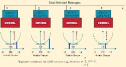
In Figure 2 below, each horizontal axisper agentrepresents a collection of normalized variables. For each agent, there are generally many different variables that affect the cost. With Agent 1, for example, the use of heating gas contributes to the cost, so a higher furnace temperature translates into higher cost. However, a certain minimum temperature is needed, or the resulting off-spec steel might be high-cost scrap.
FIGURE 2: LET'S GET MINIMALAgent 2 requires more pressure and higher torque if the billets arent maximum hot, and that would mean a higher energy cost to produce more pressure and torque. So in this case, higher temperature results in lower energy cost. Also, the rolling drums suffer faster deterioration from excessive pressure as well as excessive heat. The cost to redress or replace the drums, as well as other machine parts such as bearings, also is part of the equation.
Agent 3 is tasked to cool the rod rapidly. To obtain uniform rod properties, slow cooling is desired. Yet, the very technique of making steel requires a rapid cooling to freeze some desired crystalline properties. The cost not only is a function of the amount of cooling water needed, but is much more complex.
Depending on the rod processed and the steel quality desired, it might be desirable to operate only units 1, 3, and 5. As the rod is cooled, the outside temperature drops rapidly. Proceeding through unit 2 where no cooling is applied, the rod is back-blooming, that is, its surface temperature rises again. For best results, the surface and center temperature should remain close as the rod cools. However, since cooling only can be applied from the outside, there always will be a heat gradient. A goal of the cooperating cooling units is to minimize this gradient, and ensure that the surface temperature doesnt drop prematurely below a certain value during the total cooling process.
A sophisticated cooling model might be used to compute the initial flow for each unit.
Agents for Cooling Control
A system in which the individual components exhibit autonomy and cooperation has several key elements:
- Water Box Cooling Control transforms a rod of a given input temperature to a lower output temperature, and provides all control support for determining appropriate flows required to achieve rod temperature set points for a wide range of product parameters.
- Negotiation determines the actual set points, considering the true capabilities of each cooling unit, and requests assistance from other units if one or more units degrade.
- Valve Control is a lower-level control that ensures the individual flow request is met, if at all possible.
- Valve Control Loop designs each individual control box to always provide, within its capability, the requested cooling (flow) through a closed-loop servo control (See Figure 3 below). When a cooling unit is commissioned, a calibration is performed. The value in register Degrade is held to zero. For various Set values the feedback Flow is observed. The Trim register is adjusted until the Error is zero. The Set and corresponding Trim values are stored. This procedure records, over the operating range, pairs of Set and Trim when all spray nozzles are in perfect condition. It provides the reference for perfect operation.
- Autonomy enters a Set value. The box will look up its corresponding Trim and place it into the Trim register. Intermediate Trim values are obtained through interpolation of the two neighbors of previously stored Set and Trim pairs. As the spray nozzle openings get smaller (as a result of calcium deposits) or larger (from corrosion), the Flow will change and an Error value will build up. The register Degrade, starting from zero, is incremented or decremented to offset the Valve signal until the value in Error is zero again. At this point, the desired flow is restored, yet the value in Degrade is a measure of the degradation of the cooling unit. The goal of the closed loop servo is to maintain each spraying units cooling rate if at all possible, even in the presence of spray nozzle degradation.
- Diagnostics and Adjustments in each cooling unit will provide a measure of health through the Degrade register. By comparing Degrade against preset constants, different warning levels can be detected. Ultimately, a shutdown request might be issued.
- Cooperation. If a unit cant fulfill its requested setpoint (zero Error), its possible to measure the actual flow and request assistance from other units, increasing the Set at other units. However, degradation at this unit and at other units will remain or continue.
Cooperation Via a Mechanical Model
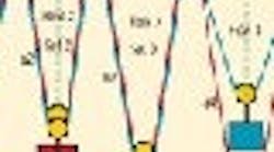
A mechanical model (See Figure 4 below) is a useful analogy to illustrate cooperation between cooling units. The mechanical model consists of a number of cascaded pulleys and equal, non-varying weights. A sophisticated cooling model based on crystalline properties and cooling gradients can be used to compute the initial flow for each unit.
The vertical drop of each weight represents the desired flow andfor an ideal boxalso equals SET. To have the mechanical model balance properly at the SET values, the horizontal spacing between rollers (two times setpoint) has to be proportional to SET. In this case, the vertical distance to the initial weight location is twice the horizontal distance between the rollers. The system is balanced when the angles between the horizontal top line and any rope section, a1 to a5, are the same. The mechanical system will find this equilibrium by itself because the pull along the rope must be the same everywhere.
FIGURE 4: MECHANICAL VISUALIZATION HELPS DEFINE ALGORITHMSVisualize this model, assuming that the total length of the rope isnt changed. If the distance between roller R1 and R2 is shortened (reduce setpoint1), then weight1 will rise, and all the other weights will drop slightly to satisfy the mechanical equilibrium. This is true for other setpoints as well. If a setpoint is increased (distance between R1 and R2 increased), that weight will drop while all the other weights will rise to accomodate constant rope length.
The length of the rope represents the overall temperature drop across the process. If more cooling is needed, the amount of rope between rollers R1 and R6 is increased. For less cooling, its decreased, simply by pulling at the right end to change the length.
The model also allows mutual assistance for a partially clogged spraying nozzle. If unit 4 is partially clogged and the Degrade is exhausted, then that unit runs saturated. The actual flow of unit 4 determines the rope length consumedhere its the short a4 section. The remaining rope length then is distributed proportionally to units 1, 2, 3, and 5. This redistribution can be observed by lifting the weight of unit 4 by hand. With the total rope length constant, the other weights drop according to their given horizontal roller spacing (Figure 4). This mechanical model can be implemented with a few algebraic equations, allowing the cooling system to self-correct and maintain adequate cooling performance even if one or more units have degraded.
The mechanical model also works for the above-mentioned case of only operating units 1, 3, and 5 by removing the weights of units 2 and 4. To obtain a certain temperature drop, the total rope length might have to be adjusted. However, to achieve the optimum heat-gradient curve for the active boxes, new setpoints for the units should be calculated using the modified model.
In many installations, heat sensors are positioned before box 1 and after box 5. In addition, a metallurgical heat-transfer model should check that the cooperation and self-adjustment provided by the model keeps the individual heat gradients in spec and, if necessary, adjust the setpoint of the violating box. Then, all other boxes also will adjust slightly to maintain the total temperature drop.
Refinements, Limitations, Benefits
The autonomy and cooperation of a group of cooling units uses a simple mechanical model. Since this model is based on linear algebra, it wont be optimal over all possible combinations. For example, if an application originally was set up for five cooperating units, but units 4 and 5 suddenly are disabled (flow indicates zero), then the linear model will adjust to provide added cooling for units 1, 2 and 3, though this might violate the heat gradient. Measures such as slowing down the rod speed or fixing the cooling units before proceeding could be needed.
Data gathered from the units, particularly from each Degrade register, can schedule units for maintenance. Depending on the degradation of each unit, its still possible to predict how many rods or what different wire diameters still can be processed at good quality. For example, if cooling capacity no longer is available for a thick wire, then a thin wire could certainly be run at lower flow Sets. So theres a graceful migration of production capability towards thinner wire.
The mechanical model serves well in making cooling adjustments for slowly decaying units, and for indication and scheduling for maintenance and restoration of deteriorated units. The cooperation of the cooling boxes reduces the manual interaction of the operator, reduces the number of test rods that must be processed before good product is produced, and allows more rods to be processed before maintenance shutdown.
| About the Author |
Dr. Ernst Dummermuth is a consultant in the areas of automation, motion control, process control and intellectual property. He has been involved in advanced technology endeavors, including architecture proposals, fast prototyping, concept verification, standardization, and product development. His work has yielded 42 patents and dozens of publications.
Read our article The Not-So-Odd Couple, by Ernst Dummermuth. This article talks about how motor and its generator are bound together. One does not exist without the other.

Leaders relevant to this article:


