You’ve probably never counted the number of connectors in your network. However, you might be surprised at just how many there are. You might be even more surprised—unpleasantly so—if you’ve been treating signal wire connectors as mere commodity items. Why? Because doing so leads to some of the stealthiest performance and downtime problems a network can experience.
We might not think much about the technology behind each connector, such as which style (see sidebar below) or termination method to use, but all can affect bandwidth, reliability, and total cost of ownership.
The Right Stuff
A sound strategy for preventing connector-related problems begins with using the right connectors. At the very least, these must be industrial-grade rather than consumer-grade.
“Home network devices are meant for conditioned environments,” says David LaBree, CTO of Prime Telecom in Tampa, Fla. “They use inexpensive components to keep prices down. Placing home devices into industrial environments is asking for problems.” Prime Telecom provides network engineering, integration, and maintenance services to municipal and ISP networks.
Manufacturers agree that your first line of defense is to go with industrial devices. Weidmüller is one of many industrial-component suppliers that make connectors suited for harsh environmental conditions, including solvents, fumes, vibration, abrasion, oil exposure, sunlight, cold, crushing forces, corrosive fluids, electrical noise, and extreme heat or cold.
Andre Jordao, Weidmüller’s business development manager for advanced connectivity in North America, says, “One of the biggest problems with Ethernet for industrial applications is that many customers chose to use common, small-office/home-office (SOHO) equipment. The pricing and availability are tempting, but those devices were designed for a clean office environment. These products were never designed to work in harsh environments. The products might work for awhile, but intermittent problems or complete failures are guaranteed. It’s only a matter of time.”
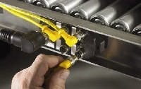
Notice the protective boots on these connectors. Your choice of protection devices and methods can affect the reliability of the connection. Expect trade-offs in cost and accessibility.
You also need to provide the proper protection for each connection. (See Figure 1) You must ask what contaminants (e.g., oil, water, or solvents) are present, and to what degree? Do you need to protect from spraying, dripping, immersion, or high concentrations? Your choice of protection devices and methods will affect the reliability of the connection. Expect tradeoffs in cost and accessibility.
Better Methods
Installation matters. “Installation errors can undermine even the best design,” LaBree says. One reason errors occur is complexity. Communication Planning Corp. (CPC), Jacksonville, Fla., is a full-service system integrator serving industrial and commercial markets. Frank Bisbee, CPC’s president, says, “The technology involved in connector hardware can be mind-boggling.” So, if you use outside installers, it’s also good advice to be certain that they know their stuff.
“Never assume your electrical subcontractor is familiar with routing and terminating network cables, even if they do it all the time,” says Chip Schaible, senior engineer at A&E Engineering. “Sit down with them and go through a few example connectors.” Based in Greer, S.C., A&E provides complete industrial automation and information services, from design through integration, to many industries.
A consensus view of the major factors for a good installation includes:
- Certification of the installers. Look for a relevant BICSI designation.
- Compliance with the relevant standards, available from BICSI and the IEEE.
- Post-installation testing with a professional-quality network analyzer (See Figure 2 below).
In addition, “Always go back with a network validation tool, no matter who does the connections,” adds Schaible.
LaBree agrees. “The client assumes the design is poor if the network isn’t running optimally,” he adds. “Optimization usually requires each leg or section of the network be tested in its parts, and then tested as a whole. Poor installation will be found in testing.”
The quality of the test also is important. “Those doing the testing need to use the right test equipment and correctly interpret the results,” Bisbee cautions.
There’s a school of thought that says you save money by conducting your first round of testing after the system has been operational for a few months. Bisbee says don’t include him in that school. “It’s more economical to test as part of the installation procedure than it is to haggle later over who’s responsible for that 18-hour downtime incident caused by a faulty connector termination that should have been discovered before system turnover,” he says.
Motivated Maintenance
Even industrial connectors eventually can succumb to environmental conditions and fail. Review your preventive maintenance procedures for adequacy based on your maintenance and repair history, the existing environment the connection is in, and the criticality of the application.
“There’s a tendency to view maintenance as a cost,” explains Bisbee. “It’s actually an investment. Downtime is a cost, and maintenance is what you do to prevent it. However, you have high ROI maintenance only when you have a complete program with correct procedures and proper maintenance intervals. Think of the millions of dollars indirectly running across the typical industrial network each month. Does endangering that revenue by ‘saving money’ through failing to maintain a lowly connector seem like a good idea to you?”
At a minimum, our experts say required maintenance functions should include:
- Infrared inspections to detect voltage loss across connections.
- Insulation resistance tests to ensure insulation integrity along an entire wiring or cabling run.
- LAN tester verification of critical runs.
- Visual inspections in junction boxes.
Also, maintenance should never re-torque bolted connections or screw terminals because this actually weakens the connection. Replace crimped connectors, rather than re-using them.
What About Wireless?
As an alternative, wireless technology can reduce connection problems, right? Not in the real world. “For every wireless access device connecting to the network, there is a wired signal connection that can fail,” LaBree says.
A wireless system propagates signals from access points, which physically connect back to equipment via cabling and connectors. The typical application requires many access points because each point has a range of only 30 m. You might need more access points to overcome obstacles and blind spots. It’s easy to forget this, and consequently minimize the importance of the connectors and terminations. This all but guarantees signal degradation.
A site evaluation is a good thing to do before implementing wireless. “In large industrial applications, you still might have to contend with cable length limitations when installing data lines to the wireless access points,” explains Charles McElhose Jr., senior network engineer with Craftix Technical Solutions. “Per EIA/TIA-568 standards, the end-to-end connection between network devices shouldn’t exceed 100 m. Lines that feed wireless access points are no exception. You'll also need to run power.” Based in Baltimore, Craftix is an IT services firm that provides data cabling and network engineering services in the Baltimore-Washington corridor.
“I’m constantly amazed at the amount of wire and connectors necessary for a wireless network,” notes Dave Lagerstrom, connectivity division director at Turck Industrial Automation.
Wireless eliminates some cable runs, but the number of connections might not decrease and might even go up.”
That’s not all. “Security issues with wireless are intense,” adds Bisbee. “Wireless has its place. I’m just saying there is no free lunch. What you might save in connector costs can come back in security implementation and administration costs.”
McEllhose agrees with this projection. “Wireless opens potential security threats,” he says. “We routinely advise adding a firewall between the main LAN and the wireless LAN, so rules can be created to prevent wireless traffic from accessing systems on the wired LAN.
Fiberoptic Alternative?
The use of fiberoptics is expanding because it offers high bandwidth, and isn’t susceptible to electromagnetic interference. However, there’s another advantage due to its simplified code compliance.
The National Electrical Code (NEC) covers fiberoptics in Article 770. Chapter 3 of these NEC rules imposes some fairly complex requirements designed to prevent conductors from overheating. Because fiberoptics aren’t current-carrying conductors, they’re exempt from these requirements (with a few minor exceptions). Of course, where a cable or raceway mixes fiber and copper, you get back to complying with current-carrying conductor requirements.
While using fiberoptics simplifies code compliance, it complicates termination procedures. Terminating to fiber is hard to do well under field conditions. The tools alone make this point clear. You typically need a fiber cleaver or scribe tool, cable and fiber strippers, polishing films, a polishing tool, a microscope, specialized crimpers, an epoxy syringe, and even a curing oven. (The sidebar below provides some helpful tips.)
If you mess up a fiber termination, the connection will probably still work, but will have reduced bandwidth. Mess up several terminations, and the entire system will lag for “no apparent reason.”
Ordering fiberoptic cables with connectors preinstalled would seem to solve this problem. After all, the factory—unlike the field—has a stable working environment. Assembly technicians can use the same procedures and tools each time. However, this isn’t the cure-all it might seem to be. For example, you must know the cable length within a fairly small margin of error because providing a glass guide for light creates routing and bending problems you don’t have with copper conductors.
Think Strategically
Manufacturers have all kinds of solutions for industrial networking connections. No one solution is best, except the one that meets the connection requirements of your particular application.
Schaible sums up how to prevent connector and termination problems. “Research and specify your connector and cabling systems, just as you would the hardware components. Never leave these details to chance.”
Fiber Methods
A fiberoptic installation normally requires field terminations. Here are some tips your installer should know:
- See if an anaerobic connector system will work for your application. If so, you can skip the curing oven and eliminate one more source of error.
- Understand that “feel” is important when inserting the fiber into the connector. You can develop feel by setting up a practice station and doing several test runs on spare cable and connectors, and evaluating the results. This also is true for the polishing.
- Set aside the notion that “if a little is good, then more is better” when using the epoxy. Too much is just as bad as not enough. Follow specifications precisely.
- Use a microscope to inspect the polished connector. The flaws you don’t catch with the unaided eye will degrade the system.
- Use a fiberoptic test set. Don’t rely on visual inspection alone, which can evaluate only the surface finish of the fiber. Other defects such as micro-bending or fiber breaks inside the connector need correction, too.
- Obviously, dirt interferes with fiber signal transmission. But so can ordinary condensation, chemical cleaners, and solvents. When planning your fiberoptic system, ask connector providers about protection methods. Note that some methods make it difficult to undo a connection. Look for an industrial-grade optical connector with an IP67-rated seal.
Connector Styles
These are the more common connector styles used in networks:
- Mini connectors have a 0.875-in (about 23 mm) barrel and 16 threads per inch. They have two to seven pins. Best application: Where space is at a premium and cables are thin.
- Micro connectors are smaller than mini connectors, and follow European standards: They have a 14-mm (0.55 in) barrel and use M12 threads. Typically, they have two to six pins, but an M12 connector might have up to 12 pins. Best application: Where the equipment being connected adheres to metric standards rather than SAE. Also useful for two-pair Ethernet.
- DB connectors come in a variety of sizes. Most common are DB-9, DB-15, DB-19, DB-25, DB-37, and DB-50. The number after the DB indicates the number of active lines the connector has, and not the number of pins. Network applications typically use a nine-pin DB-9 connector. Most computer monitors have a DB-9 connector. Best application: Serial connections. They’re commonly used for “snap-on” connectors, rather than plug-in or threaded.
- IP67 RJ45 connectors are an industrialized version of the ubiquitous RJ45 connector, the most common Ethernet connector. Two problems with RJ45 are the small contact size and the weak clips—neither of which were originally intended for industrial use. Best application: Where standardizing factory floor Ethernet with the office Ethernet is desirable and failure is tolerable.
- Narrow-tongue compression lugs provide high-quality, safe, reliable terminations, if you have the correct die for a given connector. Best application: Accommodating limited-space applications where you want lug-style connections.
- Pluggable connectors for I/O modules simplify installation, speed up maintenance, and reduce wiring errors. Common features include built-in test points, tool-free operation, integrated coding, and industrial-grade (vibration-resistant or vibration-proof, thermal cycling resistant, and corrosion-resistant) secure mechanical connection. Best application: Reduce construction time via pre-manufactured wiring harnesses (in house or outsourced), or to simplify replacement of I/O modules.
Custom cable/connector assemblies (made at the factory or by a specialty shop) allow elimination of tedious connector assembly in the field, where it’s tougher to get right. This can result in serious cost-savings up-front, plus increased reliability for the life of the installation. Consider this for projects that you can plan in sufficient detail to know the needed cable lengths and which connectors to use with each one.
Custom connectors with modular inserts can solve oddball problems. Depending on the scope of your project, you might find it cost-effective to “mix and match” the housing of one connector with the guts of another rather than doing a major redesign.
| About the Author |

Leaders relevant to this article:


