WE NEED some advice about installing redundant, DIN-rail, 24 V, switch-mode power supplies in parallel. Over the years, we’ve mix-and-matched competing brands. Lately, we’re experiencing more failures than we should. What primary device performance characteristics should we focus on? What installation tips can you offer up? This doesn’t seem like it should be a problem.
—From November 2006 Control Design
ANSWERS:
Understand the Differences
Some power supplies are marked parallel-capable, which allows the unit to be connected in parallel, but it doesn’t automatically mean the unit can do load sharing. Load-sharing balances the total load between the two supplies connected in parallel, and actually can prolong the device life as it might not operate at full capacity. Check the manufacturer’s data sheet to ensure the power supply is intended for paralleling, otherwise irreparable damage could occur.
Here’s what occurs when two power supplies are connected in parallel but don’t have load-sharing capabilities. Because of several factors, it’s impossible to set both supplies to the exact same output voltage. The unit with the higher output voltage will become the lead supply and carry the entire load current. If the switching power supply used follows a typical fold-forward curve, the output voltage will start to drop once the unit has exceeded its rated current. Once the output voltage has dropped enough to match the second supply, the second unit will start to carry current, but typically the first supply is running in an overload condition. This can lead to premature failure due to excess heat.
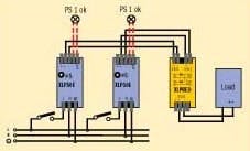
When configuring a 1+1 redundant system (See Figure 1), it’s permissible to use non-load-sharing supplies because only one unit is needed to run the load, and therefore it’s never driven into over-current. N+1 redundancy circuits should use only load-sharing devices to prevent over driving one or more supplies.
On the other hand, using two supplies that have load-sharing capabilities delivers a different result because the supplies are designed with an additional internal feedback circuit. This method is called passive load sharing. The same situation will occur in the first example with one unit having a slightly higher output voltage. However, because of the feedback circuit, the supply can sense that too much current is being delivered too quickly and internally tapers back the output voltage. The lag supply initially carries no current because the output voltage is lower than the lead supply, so the feedback circuit mechanism increases the output voltage. This back-and-forth adjustment between the two power supplies occurs very rapidly but doesn’t affect the output voltage supplying the load. This rapid adjustment is what helps balance the current between the two supplies, but the current supplied by each unit is not 100% the same. The difference in output voltages of each supply also determines how much balance occurs, and therefore the voltages should be set as close as possible to each other.
Because each manufacturer’s load-sharing circuit is designed differently, using the same power supply brand is recommended when connecting in parallel. The same design can react appropriately to the rapid adjustments to the internal voltage, and unforeseen problems can occur when two different brand supplies are used together, which can lead to premature failure.
When connecting in parallel, power supplies should be mounted side-by-side. Placing one unit above the other can cause excess heating of the top unit as heat rises from the lower. Consider using a distribution block for the load wires to prevent possible over-heating of the supply terminals and to keep the wire lengths the same, avoiding voltage drops that affect the load sharing.
Two power supplies connected in parallel offer a certain degree of redundancy, but a true redundant power supply has a de-coupling diode incorporated into the design. The diode is used to prevent a de-energized unit from becoming a burden to the remaining energized unit and also blocks a short circuit from bringing the entire DC buss down to zero volts.
Ed Merkle, engineering manager and technical support, Puls Power Supplies, St. Charles, Ill.
Know the Key Requirements
The majority of power supplies don’t have integrated capability to share current loads, and are operated so one master device carries the entire load, while a second slave device operates only when the master fails. This automatically forces the master device into a failure mode before the slave unit provides any assistance. There are many power supply manufacturers that force one power supply as a master based on setting it to a higher output voltage. We don’t recommend this master/slave approach. Instead, let the redundant power supplies share the current load. In power supplies that have current load-sharing outputs, the master and slave power supplies are preset at the factory, and share the current equally. This exponentially extends the life of both units, and is a direct result of the lower current requirements per power supply and the notably lower operating temperatures. A 10 °C reduction results in a doubling of operating life.
Redundant combinations of power supplies always should be made with identical power supplies to match the output characteristics. The power rating is the most critical consideration, followed closely by overload characteristics and current-sharing performance. This mixing of product is known to result in some power supplies operating at full power, with others not assisting at all, and leading to premature failure and thermal and current overload. Power supply designs vary significantly from family to family within a given manufacturer, as well as between different manufacturers, so great care is needed in the selection process.
Common Application Errors to look for include:
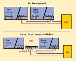
- Daisy Chaining of Power Supply Outputs. Parallel or Redundant connections never should be wired in a daisy chain from one power supply to another. The furthest downline power supply will carry the cumulative current from all power supplies, and as such have potential issues with contact current ratings, resulting thermal and safety problems. The daisy chain configuration also will interfere with the ability of current-sharing power supplies to operate correctly. This is due to the inconsistent losses associated with the wire lengths and the overall impact on the mechanism used to balance the currents. Instead, use identical lengths of correctly selected wire from each power supply to a common connection such as a terminal block. The wire lengths also should be controlled to be as short as possible, with the goal to be significantly less than 10 feet. This induces minimal voltage losses due to the wire, and also provides identical losses.
- Setting “master” power supply output voltage at 0.5 Vdc higher than the “slave” power supply output voltage. This generally indicates that the output characteristics of the power supply really aren’t intended for operation in a parallel or redundant configuration. The master would operate 100% of the time until it fails, with no assistance from the slave.
- Customer adjustment of output voltage on all redundant power supplies to precisely matching voltages. This is another indication that the output characteristics of the power supply aren’t intended for parallel or redundant configuration. This adjustment attempts to force the power supplies to perform some current sharing, but due to the electronics not being designed for this specific characteristic, the power supplies still will operate with an imbalance from power supply to power supply.
- Mixing and matching power supplies in a redundant system.By mixing a 5 A device with a 20 A device, fold-forward overload and hiccup-mode overload, and current-sharing versus non-current-sharing could create major problems in the system ranging from premature failure of some units or intermittent and unexplainable system performance glitches. Noise glitches created by power supplies transitioning in and out of the hiccup overload mode, some power supplies entering and leaving thermal overload conditions would be some concerns that would be very difficult to diagnose.
James Furukawa, project manager, industrial components, Rockwell Automation, Milwaukee
A Few Tips
There are a number of considerations that must be understood when designing a true N+1 redundant system.
All the power supplies must have the same output voltage and current ratings. Undersized power supplies can lead to current sharing, which is not the intent of a true redundant design.
The output voltage of the each individual power supply should be adjustable to allow for proper setup, and each individual power supply should be able to be operated reliably in a no-load condition. This is important since the design might require a preload to maintain the regulating circuit’s stability when a power supply is under light or no-load conditions.
When using an external redundant diode module, the rating of the module should be within the load rating of the system.
The system designer should avoid mixing and matching other vendors’ power supplies. It’s a gamble. Although manufacturers test to make sure their own power supplies can run in parallel or redundant modes, it is unlikely that any testing was done with mix-and-match of competitors’ units. Since the output characteristics probably will vary from brand-to-brand, mixing units introduces unknowns. As the reader discovered, it gives inconsistent results.
Installation tips: include adjusting the output of the power supplies such that the voltage differential between the output of the redundant unit and main supply(s) is a minimum of 0.5 Vdc. This should ensure that the redundant device is operating in a no-load condition until called on to provide power to the load.
Use a redundant diode module instead of individual blocking diodes. The diodes in the module will have similar characteristics and the thermal design optimized for the application.
Use separate power branch circuit sources for each power supply in order to achieve redundancy in the event of power loss at the source.
Dennis Jodlowski, Jim Statwick, Sola/Hevi-Duty, Rosemont, Ill.
Just Not Designed to Share
If you’re currently mixing different brands or models of power supplies in parallel, then it’s likely your products aren’t designed for load sharing and, therefore, have limited or non-existent reverse feed resistance/protection. As a result, one of your supplies is being affected by the back-feeding of voltage from the secondary parallel-wired power supply. This back-feeding eventually leads to the premature failure of the power supply due to the abnormal stress on the internal circuitry of the power supply itself.
While this basic problem can be addressed by the additional installation of supplemental, decoupling diodes, this will not ensure proper load balancing, which leads to the second most likely reason you have been experiencing power supply failures mentioned.
The best way to ensure performance and longevity of power supplies wired for redundancy, is to have equal load sharing between the devices. The ability of a power supply to share a load equally depends on the correct pairing of output characteristics with as little voltage drift (not to be confused with ripple) as possible. The output characteristics and voltage drift of power supplies can vary dramatically among manufacturers and even among different product families within the same manufacturer, regardless of current ratings.
To ensure a 50/50 balance of load sharing, use like power supplies with an output voltage difference of less than 50 mV. A voltage differential of as little as 100 mV can lead to a 70/30 load-sharing imbalance, while a differential of just 150 mV can lead to 100/0 load imbalance. This type of load imbalance can also lead to premature failure, especially if the required current output of the redundant pairing is based on the maximum rating of a single power supply.
Fortunately, these types of problems are easily avoidable by properly pairing power supplies made specifically for load sharing from the same manufacturer, same product family and same output rating.
Bruce Desmond, product marketing manager, Phoenix Contact, Harrisburg, Pa.
|
April’s Problem We Need Standards Advice |

Leaders relevant to this article:


