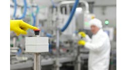
Implementing machine safety with tried-and-true hardwired components is expensive, but it is simple and effective. Machine safety with safety controllers, safety networks, and safety I/O is more complex in the design phase and can be more expensive in component cost. However, the resulting systems are cheaper to build, easier to operate, far-more flexible, and incorporate all the advantages of programmable controllers, digital networks, and smart I/O.
As the regulations governing the use of programmable controllers in safety systems in North America changed over these past five years, machine builders began to migrate from hardwired safety to some level of digital safety systems as their customers recognized the benefits (detailed in Table I below), and began pushing the machine builders to get with it.
TABLE I: BENEFITS OF SAFETY CONTROLLERS, SAFETY NETWORKS, AND SMART SENSORSProvide extensive diagnostic information to help pinpoint problems
|
The challenge is to provide these benefits at a reasonable cost by optimally implementing and integrating safety components with standard automation components.
Separate Safety
Designing a safety system that’s physically separate from the automation system is expensive. A typical separated system has an automation controller, an automation network, automation I/O, a safety controller, a safety network, and safety I/O. An HMI of some type usually interfaces to the automation controller and to the safety controller, so there’s at least one level of integration between the automation system and the safety system. This is typical of how digital safety systems were installed in their initial stages of deployment in Europe, and still is considered by many as the most-desirable design scheme.
This type of system is relatively easy to design, very capable, and provides extensive benefits over a hardwired safety system, but it’s also expensive to maintain because there are two controllers, two sets of I/O, and two digital networks.
Battenfeld Gloucester Engineering, Gloucester, Mass., makes plastic processing equipment for film/sheet extrusion. “To guard against being pulled into harms way by a dangerous nip point or roll, we use a variety of electrical components throughout our lines,” says Paul Brancaleone, engineering manager of software/controls at Battenfeld Gloucester. “Cords, photo-eyes, light curtains and crash buttons are used where they make the most sense. These often are connected to a safety relay from Pilz Automation Safety. Visible as well as audible alarming will be used to warn of any roll closures or machine movements. Our control systems monitor critical parameters in each machine such as motor loads, pressure and temperatures. For something like pressure in an extruder, we would warn the operator and halt any speed increase before reaching a critical point.”
The Simple Way
The simplest method is to use a safety controller, safety I/O, and a safety network for all machine safety and automation control. This actually could turn out to be more expensive than two separate systems, depending on the number of safety I/O points and the total number of I/O. For example, if your machine has 30 I/O points and 10 of these points are safety related, the cheapest option might be to use all safety-rated components.
Problems arise with more typical machine control applications where the bulk of the I/O is related to automation and only a few I/O points are safety-related. Again, it’s best to look at the simplest methods first, and this often indicates using a hardwired safety system.
A hardwired system generally consists of emergency stop pushbuttons, guard switches, and other safety sensors wired to one or more safety relays. An output from the safety relay is hardwired to an input on the automation controller to provide indication that the safety relay was tripped.
This is the approach used by FMC Technologies Citrus Systems, Houston, an OEM producer of citrus fruit extraction and processing equipment. “We use a hardwired emergency stop system controlling a safety relay,” says Keith Bunce, controls manager at FMC. “The safety relay feeds power to the PLC outputs, so any e-stop condition removes power to the PLC outputs.”
Bretco Electric in Milton, Ontario, is a control system integrator with specialization in motion control and safety equipment. One of its recent projects used a separate safety controller interfaced via a contact output to a PLC. The project, for an automotive parts manufacturer, used a Sick safety controller to safeguard installed CNC milling machine cells. Each cell required e-stop and door interlocks adapted according to machine type. Interfacing and monitoring was done by the safety controller, and the controller was then interfaced to a GE Fanuc CNC to advise of a fault in the safety monitoring circuit.
Jim O’Laughlin, product marketing manager, Sick’s safety interface technology group), considers various levels of safety control intelligence to recommend according to application complexity. “A key to providing the right solution is understanding the difference between a safety relay and a safety controller,” says O’Laughlin. “Safety relays are relatively mature and are used specifically in hardwired applications.”
Beyond Hardwiring
One of the problems with hardwired safety systems is that the only diagnostic information available is that the safety relay has been tripped. Given its limited diagnostic information, a hardwired system is notoriously difficult to troubleshoot. “Before we used safety networks, we had dozens of hardwired e-stops connected to numerous safety relays controlling multiple zones,” relates Mark Harned, vice president of controls for Chattanooga, Tenn.-based Astec, an OEM that designs, manufactures, and markets continuous and batch-process hot-mix asphalt facilities and soil-remediation equipment. “Safety stops routinely took 20-30 minutes to troubleshoot. Following the implementation of a Profibus safety network connected a Siemens controller, troubleshooting became fast and easy and could be accomplished on the same operator interface panel as the automation.”
Another solution is to simply layer a non-safety-rated digital network on top of a hardwired safety system. “Our Series E-connect system provides monitoring and annunciation via DeviceNet to determine where the e-stop happened and provides an output for local annunciation,” says Eric Henefield, senior product manager with the network and interface division of Turck. “The safety circuit still is a true hardwired system, it just passes information through via a connectorized junction.”
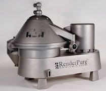
Customers expect safety-related diagnostic information from this high-speed vertical centrifuge used to separate solids and water from tallow. Hutchison-Hayes now provides this via PLC and digital network, having in the past provided just a discrete alarm contact. (Photo courtesy of Hutchison Hayes)
Many machine builders say some level of diagnostic information is becoming a requirement. “Our customers expect us to provide information about safety-related operating parameters,” says Lee Hilpert, engineering manager at Hutchison Hayes, in Houston. “In the past we might only provide a discrete alarm contact. Now we’re providing—via a PLC and a digital network—both alert and alarm information related to the process and the equipment’s mechanical condition to ensure safe operation.” Hutchison Hayes makes high-speed vertical and horizontal centrifuges (see Figure 1).
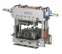
Another machine-building OEM says safety controllers and safety networks are required for most of its applications. “Because of the number of safety devices, more than 90% of our machines use safety I/O, safety bus, and safety PLC components,” says Gary Krus, vice president of Hirotec America Total Measurement Solutions, in Auburn Hills, Mich. “We use these safety components to reduce the overall cost of labor and material for implementing Category 3 safety circuits.” Hirotec makes weld assembly tooling and systems (see Figure 2 below) and measurement cells. The company used the safety PLC with hardwired circuits in 2000, and moved to the safety bus system a year or so later. Krus says choosing safety components depends mostly on the controller chosen for the machine and other customer preferences—he’s used Pilz Automation Safety, Jokab Safety, and Allen-Bradley. He currently specifies A-B for the hemming presses and Jokab for the measurement systems.
Just a Little Safety
You say your machine is typical of many in that it requires safety only for a relatively small number of I/O points, but your customers are demanding a solution easier to troubleshoot than a hardwired system. What is the best way to proceed? For many machine builders, the right path is to implement separate safety components tightly integrated with the machine automation system.
A good example of this is a motor controller with a safety controller and safety I/O built right in. “Our Rexroth IndraDrive with safety on-board integrates safety functions directly into the motor drive,” states Karl Rapp, branch manager for the machine tool industry at Bosch Rexroth’s electric drives and controls division. “The advantages to this approach include no separate safety controller or safety I/O, no contactors required on the main power or motor power lines, no additional external speed-monitoring devices, and operation is independent of the main automation system. Drives with safety on board also save costs by eliminating hardware and wiring for additional I/O.”
Integration was engineered into a SEW-Eurodrive solution for automaker General Motors from the start. Control is decentralized with an integrated drive and gearmotor housed on conveyor modules. Plug-and-play connectors eliminate wiring terminations, and simple DIP switches instead of software configure the drive. “A 24-V safety stop circuit integrated into the drive replaces traditional safety hardware components,” says Hans Rodgers, senior manufacturing project engineer for GM’s controls, conveyors, robotics and welding group. “This combination of design decisions helped eliminate local engineering and installation variations and made a global platform possible."
The SEW design allowed GM to eliminate expensive safety contactors without compromising worker safety. SEW implemented an EN954-1 category 3 safety stop through a low-voltage approach that separates the safety function from the line voltage power used to control the drive and motor. Since it is on a separate circuit, the safety stop halts conveyor motion without cutting power to the control system. With an inline installation, an entire circuit of drives could be disconnected from the host controller in the event of a safety stop. The setup lets the drives and controller continue to talk to each other.
Distributed Safety
When safety functions are more extensive, a separate distributed safety controller with safety I/O can be the best choice. Goss International, Bolingbrook, Ill., makes web-offset printing presses as well as post-press finishing equipment. “Vendors have been introducing new products such as ProfiSafe and failsafe CPUs that combine traditional control PLC and I/O components and networks with what used to be separate safety control components and networks,” says Chris Cote, Goss’ R&D electrical engineering manager. “It’s now possible to implement process and safety control in one controller across one network with a mix of traditional and safety I/O.”
The system Cote speaks of—supplied by B&R Automation and other vendors—uses a safety controller, a safety network, a mix of safety and non-safety I/O, and a mix of safety and non-safety motor controllers. This lets a machine builder pay for safety only where it’s needed.
B&R says its Ethernet Powerlink safety technology has open, safety-oriented mechanisms implemented in the data transfer process, so safety-relevant data can be transferred over a standard fieldbus. With this solution, they say safety functionality is completely integrated in the control system, doesn’t require special cabling, and all relevant standards for safe data transfer, as required by the automation industry, are achieved according to IEC 61508 SIL Cat3.
Another distributed safety system is supplied by Beckhoff Automation. This system uses a non-safety controller, a non-safety network, non-safety I/O, and distributed safety controllers with safety I/O. These distributed safety controllers, known as TwinSafe Bus Terminals, allow machine builders to implement safety in small, distributed I/O increments.
The result is a low-cost control system. “For small configurations, the tasks of a fail-safe PLC can be handled within the bus terminal system—a far more streamlined and cost-effective alternative than a traditional safety PLC,” argues Rob Rawlyk, applications manager at Beckhoff. “Both standard and safety-rated bus terminals can be configured via our TwinCat programming software.” [See the sidebar below for how one machine builder uses Beckhoff’s distributed safety system.]
Machine Builder, Customer Buy-In
Machine builders clearly buy into the integration of automation and safety systems. “We’re starting to integrate safety-rated buses and controllers into our hardware,” says Mike Harrington, director of engineering at Alliance Machine Systems, Spokane, Wash. “In the past we typically had a machine control system and then a safety system on top of it Alliance makes automation and material handling equipment for corrugated box plants.
Another benefit of these smart systems is flexibility. “Flexible safety system functions include the ability to enable only a portion of machine or process, thus preventing unnecessary exposure to hazards unrelated to the task at hand,” says Kelly Schachenman, marketing manager for safety systems at Rockwell Automation. “If a robot needs to be taught, maintenance personnel can be admitted to the cell with robot servo power enabled as long as a grip pendant is held in the proper state. If the pendant is released, then the safety system removes power from the servos. If an operator wants to enter the cell to remove an ejected part, the safety system can remove power from the servos, allowing the operator to enter the cell without a grip pendant. If maintenance needs to swap out a failed motor or perform mechanical maintenance, then a traditional lockout/tagout method can be employed.”
Using safety networks, says Astec’s Harned, “is a change culturally and in practice. Customers discover the value when they don’t have to use their voltmeters to troubleshoot everything. They could monitor from a computer and know which station was causing the problem. All they had to do was look at the operator interface. You could see all the functions, specifically down to which node was causing the problem, down to the individual e-stop. This definitely sped up our installation.”
Harned adds that overall safety functionality has made his company more competitive. In a recent presentation Harned and Astec’s CEO made to two new clients, discussions included Profisafe functionality. “It was a large part of our presentation on a new crushing machine,” he says. “Users like the simplicity of what we’re doing and the ability to monitor every safety stop and every safety device on the machine. They see benefits of less downtime right up front.”
Companies that historically viewed safety as an added expense have seen that the “safety cloud has a silver lining and have started to view safety from a business viewpoint,” says Craig Torrance, services manager at Pilz Automation Safety. “Safety is [no longer] just a cost to these companies. They see the business link to safety. Looking at safety in a business sense conjures up images of minimizing business risk in terms of compliance, downtime and potential costs.”
Latest Changes That Enable Programmable Safety Controls
Q: What changes were made to ANSI NFPA 79 to harmonize with EN IEC 60204-1 and other European regulations, and how have these changes allowed North American machine builders to implement digital safety systems?
A: In September 2006, NFPA 79 added an exception to the requirement for electromechanical disconnection of an actuator any time an e-stop is invoked. Safety PLCs and other programmable devices such as drives now are allowed to be the final switching element, provided they are designed to relevant safety standards. This change already is in effect in IEC 60204-1. With this modification, manufacturers will see a significant cost savings in terms of equipment, wiring, and cabinet space.
Q: Have any recent changes to ANSI NFPA 79 further clarified regulations for digital safety systems?
A: Section 9.4.3 has been revised with a few significant changes:
- Section 9.4.3.1 restricts the ability to modify the application program to authorized personnel, and requires special equipment or means to access the program. Acceptable means include a key-operated switch or an access code.
- Section 9.4.3.2 addresses memory retention and protection issues. Means must be provided to prevent memory alteration by unauthorized personnel. Memory loss must not result in hazardous condition. If memory retention can create a potential hazard, a battery backup must provide at least 72 hours of memory loss.
- If your equipment uses programmable logic, a means for verifying that the software is the relevant version must be provided. Rockwell Automation products meet this by letting the user apply a “safety signature,” a unique number assigned to a version of the program. When the signature is compared to documentation, the user can determine if the program has been changed.
- The failure description was revised to accurately reflect the performance of the safety-related function. In 2002, any single failure had to shutdown the system, prevent subsequent operation, or prevent unintended startup. This was based on the false assumption that all failures are detectable. In the 2007 version, the wording more accurately reflects current technical understanding of fault detection. A fault can occur, but a single fault must not lead to the loss of the safety function. In addition, the safety function must be able to monitor itself and stop the application.
- Annex A also has been revised to help clarify some of the requirements for safety rated controllers. In 2002, only IEC61508 was cited as a reference for the design of safety-rated systems using programmable safety rated devices. In 2007, the standards ISO13849-1, ISO13849-2 and IEC62061 also have been added. In addition, the standard SEMI S2 was added for functional safety requirements for semiconductor equipment.
This Q&A was conducted with Steve Dukich, global component technical consultant, machine safeguarding, Rockwell Automation.
Tire Tester Uses Distributed Safety
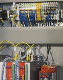
The Seichter TU machine control system allows mixing and matching of non-safety rated components (white terminals) and safety-rated components (yellow terminals) on the same digital network. (Photo courtesty of Seichter)
Hanover, Germany-based Seichter GmbH makes tire and wheel testing machinery that checks tires for dents, bulges, and other manufacturing defects. Teichter says its Tire Uniformity (TU) machine is significantly more compact than comparable systems and offers minimum cycle times combined with maximum precision. Seichter’s TU machine is controlled with an industrial PC, an operator interface panel, standard bus controllers, safety-rated bus controllers, servo drives, standard I/O, safety I/O, and EtherCat networking.
The concept of distributed safety allows the machine to be controlled by less-expensive, non-safety-rated automation components, except for specific areas that need safety-rated controllers. These controllers are networked back to the main controller via Beckhoff Automation’s standard non-safety rated digital network.
A safety fence with safety latch is integrated into the TwinSafe system to protect machine operators. TwinSafe is a new safety control and I/O system from Beckhoff that just recently received approvals for use in the U.S. In this application, the TU machine uses a TwinSafe distributed safety-rated controller and local safety-rated I/O, all interfaced to the main controller via the EtherCat digital bus.
Johann Klassen, lead engineer with Seichter responsible for engineering the TU machine, says the safety system offers potential for new and more complex applications. “The main benefits now result from significantly simplified wiring,” reports Klassen. “Emergency stops can be installed at a later stage as required. Because emergency stop circuits often are designed in advance and subsequently require modifications during commissioning, this saves money and time.”
One programming software package is used for configuring safety and general automation. “We don’t have to work with two different software packages. Since we were already familiar with TwinCat software, a simple orientation for TwinSafe was sufficient,” says Klassen. “We then were able to program the safety functions ourselves. While these aren’t particularly complex in our case, they nevertheless demonstrate how easy it is to implement safety functionality.”

Leaders relevant to this article:


