By Loren Shaum, contributing editor
In its origin, machine safety for the most hazardous machines, like punch presses and press brakes, focused on control redundancy. Clearly, equipment failure that could lead to something catastrophic for an operator or maintenance person required the statistical reassurance of redundancy. Mean-time-between-failure (MTBF) of components, first initiated by military standards, became a measuring stick for failure probability. Of course, the contradictory position is that the more redundancy, the more components you have that could fail.
Safety standards first were introduced to Machine Builder Nation in 1970 to ensure that safety-rated applications comply with minimum control requirements. The Williams-Steiger Occupational Safety and Health Act established an early measure for control reliability on mechanical power presses. It read: “The control system shall be constructed so that a failure within the system does not prevent the normal stopping action from being applied to the press when required, but does prevent initiation of a successive stroke until the failure is corrected. The failure shall be detectable by a simple test, or indicated by the control system.”
Machine safety now is driven by reasonably mature global safety standards, and the reliability of components on such equipment appears closely matched with military, aerospace and other governmental reliability requirements. So, with much more electronic reliability available, safety equipment suppliers are focusing on the value proposition of not only safer machines, but also machines, because they are safer, producing faster and cheaper than ever before.
New or Retro?
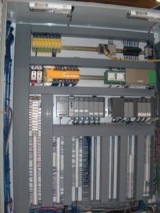
The question is when to use which type of safety device. And that decision typically is based on whether the machine is new or a retrofit and the subsequent configuration. A perfect example of this can be seen at Centerline, a builder of automated assembly, tube processing, metalworking and welding systems in Windsor, Ontario (Figure 1).
8 INTO 1
Figure 1: One programmable safety relay replaced eight and was retrofitted to a welding cell at Centerline. The relay connects to the existing machine PLC via DeviceNet.
Photo by Pilz
However, when do numerous relays give way to a controller? Is there a middle ground? And, what do you do with existing machines?
Safety Relays
For installed machines, ensuring safe operation can become a sticky issue and often is compromised in favor of sustaining production. Many safety-solution providers offer safety surveys that inform users of machines that do not meet standards and offer safety options that will place the machine in compliance. The most common solutions resulting from these surveys are machine perimeter guarding and point-of-entry guarding. However, to monitor and interlock this equipment to the existing machine control, a safe interface is required. Enter the notion of a safety relay.
Presented by Pilz Automation Safety several years ago as a redundant relay in one package instead of two electromechanical relays in parallel, safety relays not only provide Category 4 protection by monitoring emergency stops, safety doors, light curtains and two-hand control installations, but some also allow configuration to the specific application.
J.B. Titus, manager, business development and industry standards, Siemens Energy & Automation says a safety relay should incorporate:
- stop category 0 according to EN 60204-1
- two electronic enabling circuits
- two floating enabling circuits
- one electronic signaling output
- 24 Vdc power
Safety Apples and Oranges?
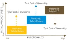
Figure 2: The costs and sophistication of safety devices will vary with the needed functionality.
Photo by Siemens
When the emergency stop control switch is activated, outputs switch off. The outputs are switched back on again when the e-stop control switch releases, the protective door locks, a feedback circuit is closed and a start button is activated.
When the protective door enable is activated, outputs are switched off and solenoid control outputs are switched on with a time delay. Then the protective door is released. When the protective door enable is activated once again, the solenoid outputs are switched off and the protective door is locked.
The more safety devices that are required, the higher the likelihood of incorporating a safety controller instead of continually adding more safety relays. “The choice is based primarily on the number of safety points,” says Titus (Figure 2). “Invariably, more than eight to 10 safety points favor a safety controller.” Because relays are still mainly electromechanical, they can fail. So using fewer relays makes sense.
The Gray Area
Relays specifically monitor and communicate the status of machine-mounted safety interlocks with installed controllers. “The term ‘relay’ is confusing to many users because they envision a traditional electromechanical device,” says Mike Carlson, safety products marketing manager at Banner Engineering. Banner’s muting “module” can suspend safeguarding during a safe period and allow objects to pass through a light screen without triggering a stop. This muting function puts the module in a gray area between a relay and a controller. Some intelligence is added to allow a relay to mute based on an external stimulus. Such requirements are common in retrofit applications.
ASK THE RIGHT QUESTIONS |
When choosing a safety system to comply with standards, Siemens suggests these considerations.
|
- any PLC works, so it’s not necessary to replace the installed PLC with a safety-rated PLC;
- all existing PLC code running the machine logic will still operate;
- since safety interlocks are an additional function on the AS-i bus, diagnostic rungs can be added;
- the PLC can read all diagnostic data from the safety monitor; and
- since the installed PLC is unlikely to be a safe PLC, the safety logic remains in the safety device.
Output safety contacts are monitored internally in safety relays from Omron Scientific Technologies. If a fault occurs in the operation of one of these contacts, the safety monitoring relay shuts down, removes power from the machine primary control elements (MPCE) and prevents a start or successive cycle of the machine until the fault is cleared.
“Safety monitoring relays are designed to provide a convenient and economical solution for incorporating control reliability into a safety circuit,” says Rich Puddicombe, product manager at Omron. “Power to the MPCE is connected through the safety output contacts of the safety monitoring relay. Inputs to the safety monitoring relay are typically from safety devices such as emergency stop switches, limit switches or safety interlock switches.”
Pilz also has expanded its safety strategy with a PNOZmulti safety relay, which is configurable to multiple functions. It also can perform some standard control functions, making it a mini-controller of sorts, designed for smaller new machines, as well as retrofits—yet another device in that middle ground between the relay and the controller.
Safety Controllers
If a builder is restricted to retrofitting or smaller machines, relays make sense. Dave Cole, president of Cole Controls (colecontrols.com), a system integrator in Fort Wayne, Ind., prefers relays in the retrofitting projects his company does at Chrysler plants. “I’ve only used safety relays in systems so far, but I can see some real benefit with safety controllers if the application requires a large number of safety interlocks,” says Cole. “However, smaller machines don’t need elaborate safety systems.”
But when the safety points reach critical mass, it could be time to move up to an alternative.
“When you have a large number of safety points to monitor and diagnostics become critical, there is little doubt that the safety controller is the way to go,” says Siemens’ Titus. He also points to a key issue for deploying safety relays on new machines. “Machine builders must be aware that installing safety relays on new machines requires third-party certification to ensure compliance to all applicable standards before shipping the machine.”
Safety on the Network
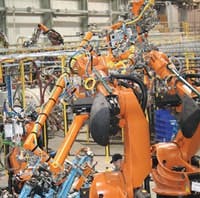
Kuka Flexible Production Systems, a Sterling Heights, Mich.-based producer of automated/robotic production systems for car bodies and chassis, was tasked with designing Chrysler’s Toledo Production Operations assembly plant using a design, build, own, operate and maintain philosophy with no restrictions placed on equipment used (Figure 3). The sole criterion was to use only field-proven technology.
Field -Proven Tech
Figure 3: Kuka chose a distributed safety network because of numerous safety points at Chrysler’s Toledo Production Operations assembly plant.
Photo by Kuka Flexible Production Systems
Based on the number of safety points, their location throughout a specific work cell and the complexity of the overall cell control, Kuka chose a distributed safety network with safety relays installed remotely and communicating to a master safety controller.
Another factor was a need for high diagnostic capability. Combining both machine safety and machine control on one fieldbus eliminated centrally located relays, creating significant reduction in control panel space, hardware, engineering, design, troubleshooting and overall wiring costs.
Kuka chose Profibus to communicate with all field components, including safety devices.
“We built the system in no time and commissioning was surprisingly easy,” says Rod Brown, engineer at Kuka.
“This approach has saved us tens of thousands of dollars on the first installation alone.”
Also, take our Web poll
The choice for many machine safety applications can be redundant relays or a programmable safety relay or controller. Which one is closer to your comfort zone? Add to the discussion about this on Machine Builder Forum at ControlDesign.com/safetydevices.

Leaders relevant to this article:

