Read our April 2008 article "FPGA Can Speed Development."
By Paolo Catterina, EUROelectronics
EUROelectronics develops and sells electronic systems, including control software both for PC and PLC platforms. For several years we have focused mainly on developing electronics for diecasting machine builders. We build and install the complete electrical-electronic control cabinet including PLC and PC software for all the applications we develop.
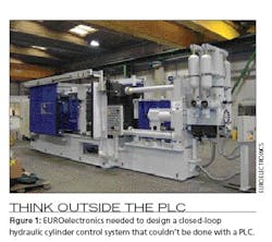
We are a highly specialized company in this sector and work together with OMS Presse, which began building machines three years ago, after 30 years as a rebuilder. Together we produce systems and presses ranging from 200 to 2,500 tons (Figure 1).
Recently, EUROelectronics was asked to design a closed-loop hydraulic cylinder control system for a die-casting press machine. In order to meet performance parameters, we needed to think differently about our control solution.
The “Before”
We previously used a Moog programmable controller with a Moog servo valve. It was difficult to program and had limited functionality. Although the system did function—we had about 15 installations in Italy and Spain—we were unsatisfied enough to look for a different solution. We had problems with the electronics and had to replace three of the controllers.
The biggest reason for a new control approach was the need for more complete control of the hydraulics by extending PID to control pressure. We also saw the need to have a more standard product and programming tool.
Why Speed Matters
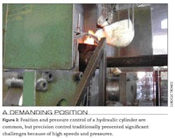
Position and pressure control of a hydraulic cylinder is a common application in the industrial automation field, but the precision control of such systems traditionally presented significant challenges because of their high speeds and pressures.
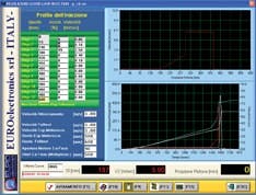
In our application, the cylinder moves over a software-defined trajectory with specific velocity and acceleration profiles. We must guarantee accuracy and repeatability up to a maximum speed of 10 m/s. For reliable control of cylinder braking and acceleration, closing of the loop must be at 1 kHz processing rates (Figure 2).
Necessary Profiling
Figure 2: For reliable control of cylinder braking and acceleration, closing the loop must be done at 1 kHz processing rates.
Photo by euroelectronics
In a high-speed, closed-loop control system such as this one, the quality of sensors required for pressure measurement and positioning is critical. In this case, we selected linear magnetic strip sensors for position measurement. These sensors must be highly precise and reliable, and the signal processing interface for the sensor signals must be fast and rugged.
The FPGA Alternative
We were attracted to a possible FPGA-based solution by some tests done by National Instruments in Milan. Their engineers demonstrated a deterministic cycle time under 1 msec in an easy and interesting way.
The compactness and modularity of the NI CompactRIO hardware was attractive, but the most important factor was its FPGA architecture. It seemed very quick and robust enough for the application. The high-speed press moves 0–10 m/s and therefore requires high-speed control.
We choose NI because I had been using its data acquisition cards as far back as 1993. Roughly 1,500 of the systems we have developed are PC-based platforms, about 700 with an NI acquisition card. We installed eight systems with the FPGA solution during 2006-’07, and in 2008 we have orders for 10 more systems using this approach.
PC: Not for Motion Control
We never considered a PC-based motion controller as a possible solution for this need. In our experience, the PC is the least-reliable component in the complete electronics package we deliver and we prefer more robust and dedicated devices.
We’ve developed the software on a PC using LabWindows CVI, starting from DOS version to the current Windows-based platform. I always have been happy with NI hardware and software, so I wanted to move forward with NI products.
Although our five PC software programmers use LabWindows CVI, my experience started in 1992 with a LabView DAQ application for a diecasting machine, which was sold to China that year. Although many years passed, I realized significant advantage by drawing on my experiences while developing this new application.
With the integrated FPGA on the controller, we developed a system capable of low-level customization using commercially available tools. To meet the unique requirements of the application, we implemented a highly optimized encoder interface in the FPGA to measure the cylinder position while programming the system entirely in LabView.
The FPGA solution controls only the injection piston movement (Figure 3). Other movements and overall features are controlled by a Siemens PLC, which is our standard for diecasting plants.
How It Works
The system controls the cylinder position to track the velocity and acceleration trajectory values the operator enters. The operator can control the cylinder movement through a PID algorithm. The pressure sensor feedback is in the order of a few msec, which is matched by the processing speed of PID running on the FPGA.
The motion profile and other parameters are shared via Ethernet, with a PC running a complete supervisory software application for the machine.
We control piston position using two high-speed inputs together with a magnetic strip position transducer and created a very powerful virtual encoder. This is a very strategic component.
For example, when the piston moves at 7 to 8 m/sec then every msec it has a displacement of 7 to 8 mm. The sensors have a resolution of 1/10 mm, so we must read 70 to 80 pulses in a msec. The high-speed input modules worked very well and we also tested them at 10 to 12 m/sec speed and never lost any values. This aspect is important because in traditional applications we used analog input sensors (0-10 V represents 0-1,000 mm) but we encountered noise problems and insufficient accuracy.
We also read two analog inputs from pressure transducers to control the plunger’s pressure value backward and forward. A 0-10 mA analog output signal activates the hydraulic servo valve that actuates the piston movement.
A proportional value for pressure intensification is activated for final pressure PID via another analog output. Eight to 10 digital I/O are used for the interface with the Siemens PLC for manual movements, startup profile movement, piston back position, some diagnostics, intensification agreement and other movement during the cycle.
The PC-based supervisory control system sends position-speed-pressure profile instructions to CompactRIO via Ethernet. CompactRIO reads piston position through the virtual encoder and commands movement acting on the electrovalve via analog output using a PID algorithm. This movement requires accuracy in position and speed and operates in a few msec, so it can’t be controlled using a standard PLC.
All other machine movements, such as closing and opening die platen, are controlled by the Siemens PLC. These cycle times can be 20-30 msec and the speeds are not as critical as for injection piston movement.
Software Considerations
We implemented the operator interface with LabWindows/CVI. This software provides diagnostic and machine monitoring features by measuring motion quality and repeatability, performing industrial data acquisition measurements of the process variables—positions, speeds, pressures, temperatures—and reporting statistics for quality certification.
The analog input modules available with CompactRIO have excellent accuracy and precision, and we were able to fully implement the encoder function for cylinder position control using just two high-speed digital inputs.
The FPGA allowed the encoding position signals to be input directly from the sensors. We did not need an intermediate processing or amplification device, and, as a result, we achieved a noticeable reduction of noise and a corresponding increase in processing speed.
The cylinder movement must precisely follow the position, speed and acceleration profiles predetermined by the supervisory software. In a process cycle faster than 1 msec, the valve position is measured, the speed is calculated, both are compared to the set point, and the movement is corrected using a PID algorithm. To keep the hydraulic circuit balanced, pressure values in the front and at the back of the cylinder are simultaneously controlled to avoid instantaneous peaks.
The application’s ability to effectively close the loop over the hydraulic servo valve is possible only if the processing cycle time is absolutely deterministic. Likewise, the hydraulic circuit must respond quickly, precisely and repetitively. In this case, the hydraulic servo valve was controlled through an analog output signal.
Since the supervisor software acquires the real movement and pressures of the piston during injection and traces a diagram of real measured values, no automatic feedback/correction mechanism exists. We felt this would generate process instability.
Instead we calculate a dozen control parameter values to establish a tolerance range that determines if the injection is good or not. After that, the extractor robot brings the piece to the good-piece basket or the scrap-piece basket.
The precise tuning of the PID algorithm was obtained through the calculation of a linearization table of the response values for the valve, which has unique nonlinear behavior. With this PID gain scheduling method, we could obtain very accurate responses both at low velocities (0.05–0.30 m/sec during the start movement of the cylinder) and at high velocities (real maximum speed reached is 7.5 m/sec).
Using feed-forward and smoothing techniques on the command signal, we also were able to calibrate the PID algorithm so that in rapid commutation points—the positions at which the cylinder must increase or decrease as quickly as possible—the risk for movement instability was eliminated.
Through the controller Ethernet port, the embedded LabView system is able to communicate with the supervising application. An operator can define the injection profile for the cylinder in two different ways with the supervisory software: by inputting numerical values or by drawing the profiles interactively using a graphical procedure. The operator also can set various parameters required to perform the machine cycle, including position, velocity, pressure and time.
Using an NI data acquisition board, we also added a number of diagnostic signals to the supervisory software, such as the position, pressure and temperature profiles for each injection. The machine-monitoring software provides plots of the machine operation and calculates various control values such as position of speed commutation, mean and peak velocities, times, pressures and temperatures.
Statistical process control is provided for further production analysis and some specific strategies are implemented to immediately stop the production when the machine goes on producing scrap pieces.
Training and Orientation
The programming environment made it easy to implement the most critical parts of the motion control system with very high-speed processing. We could implement command and feedback control without resorting to low-level development tools, custom circuitry or programming languages other than LabView. We were able to encapsulate the system into a small, complete and rugged device. We also were able to achieve significant improvements in process yield thanks to the advanced control capabilities that system enabled us to implement.
Project and development time required for this application was significantly reduced thanks to this integrated approach for homogeneous development with this software and hardware combination. We went from prototyping to the final setup of the machine in only three weeks.
I studied LabView and CompactRIO manuals for two weeks before getting the system on my desk. With the Moog servo controller, I spent eight weeks building an application, which did less and had less-extensive features and its programming kit was really difficult. That device, in fact, no longer is in production. In September 2007, Moog ended sales and support for the PS2 servo controller. Its replacement has a different programming environment. For me and my colleagues, it is very important to keep the programming tools limited in order to have a common knowledge base.
A Future Thought
At some point, I would like to build an entire machine control system based on an FPGA approach. I think technically and economically it would be quite easy to do.
The only drawback is that the Siemens S7 PLC is pretty much a de facto controller standard for European die casters, particulary since the maintenance people, technicians and so on are trained to work with it.
Paolo Catterina is a software development engineer for EUROelectronics srl in Nave, Italy. You can contact him at [email protected]
Migrating to FPGA-based control might be a tougher choice if you don’t have prior experience with the supporting vendor, as did EUROElectronics. Would you make a switch of that sort without that past experience? Tell us why at ControlDesign.com/fpga.

Leaders relevant to this article:
