The name black channel comes from the concept of a black box. The intent of both a black box and black channel is that what goes in one end does not see anything between the inlet and outlet as it passes through the device. The difference between the two concepts is that, rather than a black box piece of hardware, it is the network itself that must appear to not be there. The bus system, therefore, does not perform any safety-related tasks but only serves as transmission medium.
If the various safety bus protocols followed a white-channel scheme, this would require that the bus networking and protocol be designed from the ground up for safety. That means all the network components must be safety-related and need the associated approvals. Network components include — in addition to the end devices or nodes themselves and the logic solver — the interface converters, attachments and couplers, repeaters, safety barriers, bridges, hubs, switches and routers.
| Measure | ||||
| Error | Consecutive Number (sign of life) | Time-out (width acknowledgement) | Codename (for sender and receiver) | Data Integrity (CRC) |
| Repetition | X | |||
| Loss | X | X | ||
| Insertion | X | X | X | |
| Incorrect Sequence | X | |||
| Data Corruption | X | |||
| Delay | X | |||
| Masquerade (standard message mimics fail safe) | X | X | X | |
| FIFO errors in intermediate routers | X | |||
| *No acknowledgement from routers (lower levels of OSI Model) | ||||
|
Table 1 |
||||
The black-channel concept uses a non-trusted transmission system; the network gear is not safety-related. As a result, the primary advantage of the black-channel concept is we can reuse regular network hardware for safety networks without having to modify more than the devices or nodes themselves.
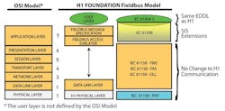
No changes to any of the Physical Layers means the safety measures must be added as a safety layer on top of Open Systems Interconnection (OSI) protocol Layer 7, thus increasing the size of that layer. The new layer is responsible for the transport of safety-relevant data. The remainder of the application layer is responsible for acquisition and processing of user or process data.
As shown in Figure 1, the black channel uses a safety layer between the communication stack and application as per IEC 62280-1. This concept originated from railway signaling technology. The safety layer performs safety-related transmission functions and checks on the communication to ensure the integrity of the link meets the requirement for SIL 3 continuous/high-demand mode. Though unlikely to be done, it is possible to use the black-channel concept with some non-safety-related devices sitting on the same bus and sharing the communication media. So, if someone accidentally connects a non-safety device to the safety bus, it will not negatively impact safety operation.
Figure 1
The black channel uses a safety layer between the communication stack and the application.
This means that none of the error-detection mechanisms of the chosen communication technology are taken into account to guarantee the integrity of the transferred process data. Basically, there are no restrictions on transmission rate, number of bus devices or transmission technology — as long as the given safety application reaction times can tolerate the additional overhead parameters.
Detecting corrupted data bits through an additional cyclic redundancy check (CRC) plays a key role in meeting safety bus reliability requirements. The necessary probabilistic examination can benefit from the definitions within IEC 61508 that consider the probability of failure of the entire safety function. Because a safety circuit includes all sensors, actuators, transfer elements (this is the safety bus) and logic processes that are involved in the safety function, and IEC 61508 defines overall values for the probability of failure of the system for different safety integrity levels, then some fraction — typically 1–2% — of the overall SIL rating is assigned to the transfer element, which is the network equipment or black channel. For SIL 3, the probability of failure is 10-7/hr. If transmission uses 1% of the permissible probability of failure, the probability failure rate for the safety bus system must be 10-9/hr. By selecting appropriate CRC polynomials for the intended frame length, the resulting residual error probabilities of the undetected corrupt data packets is guaranteed to meet or exceed the required limits. We are no longer depending on the basic error detection of the standard fieldbus protocol (white channel) because we have added the supplemental checks shown in Table I on the system communications to identify the sources of transmission errors on the network.
The measures in Table I indicated in the appropriate columns, other than CRC for data integrity, check for a range of other types of communication errors that can arise during transmission of a message between any two points. Each of these measures as implied by the short explanation in brackets provides the following benefit and increase in confidence of the reliability of the transmitted information:
• Consecutive Number — Confirming that the message transmitted is received and reassembled in the proper sequence is important, especially for messages that have the option of more than one route (such as with Ethernet) to get from point A to B.
• Time Out — Many buses have some form of acknowledgement mechanism. However, the majority of the industrial Ethernet protocols use User Datagram Protocol (UDP), which does not support message acknowledgement. Therefore, an independent, dedicated tool must be used.
• Codename — This is a way to be sure messages are transferred between the two end devices/nodes for which they are intended, and no others.
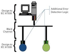
Figure 2
The safety measures are encapsulated in the communicating end nodes/devices as shown.
The functionality of the safety protocol is not concerned with which transport protocol (Foundation fieldbus H1, Profibus-DP, Ethernet, etc.) is used to transport the safety frames because all safety-related mechanisms are integrated exclusively on the application layer of the protocol, and the safety bus functionality is independent of the underlying transport layer.
The safety bus network does not benefit from any error-detection mechanisms of underlying transmission channels and thus supports the securing of whole communication paths, even backplanes, inside controllers or remote I/O.
The black-channel approach ensures that the safety quality is independent of the communication channel.
The black-channel concept really isn't black magic. At most, it's a "sleight of hand," since just like the black box, a black channel moves responsibility for making the "trick" work from the medium or messenger to the parts of the system that actually do the work and have the intelligence to tell the difference.

Leaders relevant to this article:


