How do you provide overload protection for variable-frequency drives?
June 15, 2018
8 min read

What strategies do you recommend for overload protection when employing variable-frequency drives?

Jack Zurick, senior control systems engineer at Thermo Systems, a Control System Integrators Association (CSIA) member: We need to distinguish overload protection from over-current protection. Over-currents are due to a short circuit. Overloads are due to running overcurrent which causes overheating. The devices used to protect each type of overage are different. Magnetic circuit breakers, fuses and over-current relays are commonly used to provide over-current protection. Overload protection is a protection against a running overcurrent that would cause overheating of the protected equipment. Overload protection, is usually built into the drive and needs to be adjusted according to the manufacturers recommendations. As far as over-current protection, most manufacturers will indicate how to size the circuit breaker or fuses protecting the variable frequency drive having taken into consideration their drive and the National Electric Code. In the case where the variable-frequency drive has a bypass provision, external overload protection should be provided.

Chip McDaniel, technical marketing at AutomationDirect: Overload and other forms of protection for the VFD, the motor, factory personnel, and the surrounding equipment include a properly sized power supply, the right grounding system, fusing, disconnects, and contactors. Input fuses protect the AC drive from excessive input current due to line surges, short circuits, and ground faults. They are recommended for all installations and may be required for UL-listed installations. See the attached diagram for an overview of VFD protection in all its forms.

Joel Kahn, product manager, inverters, at Lenze Americas: Modern VFDs make this quite simple. They incorporate motor overload algorithms. Simply enter the correct motor data into the VFD’s parameter settings and the VFD will measure the motor usage by its current load. In addition, many VFDs can also take a signal from a motor thermal sensor and trip the motor based upon actual motor temperature.

Chuck Fernandez, enclosed low voltage product manager at Siemens: Most modern VFD have internal overload fault detection using an I2t algorithm to calculate a motor overload condition. In addition, the current limit in the VFD can be set to limit the current output of the drive to protect the drive, motor and machine mechanics. Normally, a VFD is capable of 150% output current for 60 seconds. But that does not mean the motor or the mechanics in the system can withstand that much torque. So, the current limit parameters in the drive will allow a user to further limit the drive.
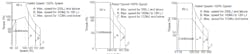

Chris Jaszczolt, industrial drive product management at Yaskawa: A variable frequency drive will provide electronic motor overload protection. This means the drive will measure motor current and monitor it electronically to limit overheating of the motor. The drive must be set up properly for the motor's full load current to operate correctly. There are typically several levels of thermal overload protection that the drive can provide. Graphs are available that depict the various thermal overloads a drive can provide (Figure 1). These overloads are typically classified by motor type. Certain motor's cannot operate at constant torque (rated current conditions) throughout their speed range. These motors have reduced speed ranges (typically 10:1 or 40:1) and follow the current required to meet the demands of a variable torque applications. A VFD can be programmed to provide thermal protection for each of these motor designs. VFDs also provide ground fault, phase loss, and over current protection for the motor. Moreover, VFDs have additional user defined protection methods. These methods can detect pre-set over/under current/torque conditions to provide quicker motor/load protection than the drive's thermal overload. Finally, external thermal overload protection should be used when operating more than one motor with a singular drive.

Tim Lusha, senior EMC engineer at DLS Electronic Systems: Many off-the-shelf VFDs already employ overload protection. This can be set to the desired rating for the specific motor. Fast blow fuses or circuit breakers can also be used as a means to do this.

Richard Lopez, senior applications engineer at American Control Electronics: Most modern-day VFDs already offer internal motor overload protection capabilities. Since VFDs are constantly monitoring motor current, their internal circuits are the first line of deference when a motor becomes overloaded. VFDs typically have adjustable current/torque threshold adjustments where if a motor exceeds them, the drive will reduce power to the motor in an effort not to go deeper into an overload condition. Some VFDs will fault out or trigger an alarm when an overload condition exists for a prolong period of time. Even with these active monitoring circuits on a drive, it is also recommended that external fusing or circuit breakers be used to protect the drive and motor. We also always recommend being aware of local codes that can dictate the type of OL protection that is required.

Chris Cusick, senior VFD product specialist at Mitsubishi Electric Automation: Generally the drives own thermal overload protection system is the simplest and best way to accomplish protection. Separate overload relays would be used for multiple motor applications. The drive is then set up so that it will trip if any of the overload relays open—a circuit wired in series.

Rick Akey, senior application engineer, low-voltage drives groups, at ABB: VFD’s typically provide electronic overload protection for motors via their internal firmware. With proper set up and commissioning of the drive parameters, the motor can be protected from overheating due to excessive load or other conditions that might cause the motor to run above its Full Load Amp rating. When an overload condition is detected it could lead the drive to give a warning or a fault. Another method for protecting motors would be for the drive to monitor thermostat sensors that are placed in the motor and to use that feedback to warn or fault. The above methods are good for an application with a single motor on a drive, but in cases where multiple motors are connected to a drive, motor overload protection needs to be handled a bit differently. In this case individual motor overloads are required and if one of the motors is in an overload condition, that motor’s protection device should open a set of contacts that are wired back to a digital input on the drive so it can indicate there is a problem with one of the motors.

Nisha Chandrasekharan, portfolio manager for low-voltage drives at Rockwell Automation: Variable frequency drives can operate as motor protection devices as well as motor speed controllers. Most variable frequency drives have short-circuit protection either internally or specified externally to provide protection in the event of a fault. Users should apply fast-acting fuses in front of the drive for short-circuit protection to minimize the let-through energy, in the event of a short-circuit event. Other protection devices that have been qualified and tested (typically to UL standard) are listed in VFD technical documentation manuals for application engineers according to their requirements.

Tim Albers, director of marketing and product management at Nidec Motor: All VFDs come with both some level of alerting, shut down and droop modes in the case of overload. The process demands and safety should drive how those are implemented. In some cases shutdown may be the only solution, in others, droop may be the only option. Being aware of the control options is key to employing the most optimal solution. Having external thermal protection on the motor that is directly connected to the VFD is also recommended.

Margie Rawlins, lead control systems engineer at Thermo Systems, a Control System Integrators Association (CSIA) member: Most drives have overload protection incorporated in them. If the drive’s parameters are set correctly, this is often enough. If, however, you are using one drive to control multiple motors, the current/ overload setting will need to allow enough current for all of the motors, which means that it will not supply any overload protection to the individual motors. NEC code requires each motor to have its own circuit protection in these cases.

Steve Perreault, industrial drive product management at Yaskawa: Most VFDs have electronic motor overload protection for standard motor types. This electronic protection is generally superior to conventional physical overload relays because the VFD generally has knowledge of motor type and motor speed, and thus can optimize protection. Additionally, many VFDs can accept temperature feedback devices for even more accurate protection. For HVAC applications, where a VFD is combined with a bypass, an overload relay is usually applied when the circuit is in bypass mode. In addition, the FVD also protects itself from overload by employing current and temperature sensors.

Mark Harshman, director, systems engineering, at Siemens: If the drive is always operating the motor, typically the VFD control will have its own inverse thermal protection algorithm and instantaneous current overload protection built in. However, if the VFD is used to start the motor and then transfer it to the utility, a commercial motor protection relay (MPR) must be supplied, usually as part of the switchgear used to connect the motor to the utility once the VFD has accelerated the motor up to full speed and synchronized it to the utility. There is also the capability to use a commercial MPR with the VFD if additional motor protection features in the MPR are desired. In this case, the MPR trip function is connected to the VFD control allowing the VFD control to trip if a motor condition is detected by the MPR.
About the Author

Mike Bacidore
Editor in Chief
Mike Bacidore is chief editor of Control Design and has been an integral part of the Endeavor Business Media editorial team since 2007. Previously, he was editorial director at Hughes Communications and a portfolio manager of the human resources and labor law areas at Wolters Kluwer. Bacidore holds a BA from the University of Illinois and an MBA from Lake Forest Graduate School of Management. He is an award-winning columnist, earning multiple regional and national awards from the American Society of Business Publication Editors. He may be reached at [email protected]
Sign up for our eNewsletters
Get the latest news and updates
