“Servo bandwidth” is a very common term used in the motion control industry. The value is often used as a specification to characterize a servo loop’s performance. But not all servo loops are asked to do the same job, causing confusion as to which servo-loop metric accurately defines the requirement. First, the components of a servo loop need to be defined to set the stage for a discussion of bandwidth vs. loop gain. Also, a description of the open- and closed-loop transfer functions will help us to fully grasp the fundamental differences between bandwidth and loop gain. Bandwidth and loop gain can be used to characterize performance of servo loops. An example can show how two systems with identical bandwidths reject a disturbance frequency with different degrees of success. But bandwidth and loop gain can be used incorrectly when discussing aspects of a servo system.
Servo loop
Before we dive into bandwidth and loop gain, let’s start with the basic word “servo” and what it means. Engineers will often use the term “servo loop” to describe any type of closed-loop control system, whether it be a dc motor and encoder or a piezoelectric stack actuator and capacitance probe. In this case, the word is typically used as a noun. An example might be: “The servo is stable and performed the move within its allotted time requirement.”
The word “servo,” however, is sometimes used as verb. For example, an engineer might say, “The stage ‘servoed’ to the final position without any problem.” The word “servo” is commonly meant to represent the entire closed-loop system, meaning the actuation device, the sensing device, the drive and control electronics and the control algorithm.
Figure 1: The basic servo-block diagram is applicable to most electromechanical servo systems. The five main elements to the servo system are the controller, drive electronics, actuation device, plant and sensor.
Figure 1 shows the basic servo-block diagram applicable to most electromechanical servo systems. There are five main elements to the servo system:
-
controller
-
drive electronics
-
actuation device
-
plant
-
sensor.
The controller is the brains behind the servo system. It is regulating the direction and magnitude of control effort that is needed to arrive at the desired goal. The desired goal in all servo systems is to reduce or minimize error. The drive is the component that converts low-voltage electrical signals from the controller into high-power current or voltage signals that deliver power to the actuation device. Common actuation devices for electromechanical servos are dc motors, linear and rotary, and piezoelectric actuators. These devices are often built into or coupled with more complex devices such as valves, gear boxes or bearings. The fourth component is the plant. The plant is the structure that supports the actuation device and the sensor. It includes the moving load that the actuation device is connected to.
The last component is the sensor. This component converts a physical metric, such as position, velocity, pressure or flow, into a signal the controller can use as an input—voltage or counts.
Closed-loop transfer function
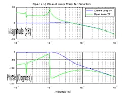
The closed-loop transfer function (CLTF) is the most common way to describe the control system in the frequency domain. The data is taken while the loop is closed, thereby capturing the closed-loop dynamics in the transfer function. The gain of the CLTF is very close to unity at low frequency and rolls off at high frequency, with some amplification in between, depending on the phase margin of the system. The phase of the CLTF is near 0 at low frequency and more negative than -180° at high frequency. This curve is typically used to state the system’s bandwidth. A simulated CLTF is show in Figure 2.
Figure 2: The CLTF curve is typically used to state the system’s bandwidth.
Open-loop transfer function
The open-loop transfer function (OLTF) is representative of all the frequency-dependent blocks that make up of the servo loop, meaning the control, the drive, the plant and the sensor. The OLTF for some systems can be taken with the servo loop open, but, in many cases, it must be either derived from models or taken with the loop closed using the test point in Figure 1. The OLTF can be found from the closed loop using the formula, CLTF/(1-CLTF), where CLTF is the complex representation of the closed-loop transfer function. Referring to Figure 1, the CLTF can be measured by driving the system with random or swept sine at In2 and measuring Out2/In2. The OLTF can be found by driving with In2 and measuring Out2/Out3. The open-loop and closed-loop transfer function are shown in Figure 2.
Loop gain
A servo gain is attributed to each component in the servo loop. The gain may simply be unity or may be much lower or higher by many orders of magnitude. There are many types of gain in a servo loop. Some gains are frequency-dependent and some gains are constant at all frequencies. The most notable servo gains are control gain, drive gain, motor gain, plant gain and sensor gain. Every servo gain gets multiplied together to create the overall loop gain. Changing any one component will affect the closed-loop stability. Some gain examples are component-specific:
-
For an encoder, the gain would be counts per micron.
-
For a capacitance probe, it would be volts per micron.
-
For a rotary motor, the motor gain would be Newton-meter/Amp.
-
For a current drive, it would Amps/Volt.
Bandwidth
Servo bandwidth describes the maximum frequency at which the control system will exert beneficial effort into a control system. Electrical engineers who deal with low pass filters, such as Butterworth, elliptical or Chebyshev, will often quote the -3 dB magnitude frequency as the filter’s bandwidth. The equivalent for servo systems would be the -3 dB point of the closed-loop transfer function. This definition, however, is not universal. Many controls engineers will refer to the 0 dB of the open-loop, or loop, transfer function as the control system’s bandwidth.
Be clear by what you mean. Are you quoting the -3 dB point in the closed loop or 0 dB in the open loop? Ask what others mean when they use the word, so there is no miscommunication that results in overdesigning a control system or having one not meet its intended performance.
In control textbooks, bandwidth (BW) is described as a characterization of a system’s response time. BW = 0.35 * TR, where TR is the rise time, is the most commonly quoted formula, but it’s also the most commonly misused formula when describing closed-loop mechanical systems. This formula is for first-order systems; and closed-loop motion-control systems do not act like first-order systems. Using the formula can absolutely steer one in the wrong direction.
There are many variations of the bandwidth formula that consider the system’s damping ratio zeta. Zeta for a closed-loop system is related to the phase margin of the system.
Almost all the formulas you will find equating bandwidth and response time for second-order systems are based on linear systems that are not in saturation. If one compares response times from actual step-response data to the calculations made via bandwidth formulas, they will rarely be equivalent; and the most likely reason is from voltage or current saturation. Drive systems have a limited amount of voltage or current; and, if the step values chosen in combination with the proportional and integral gain are too large, voltage or current saturation will occur, slowing down the system’s response versus the formula’s predicted response time.
Bandwidth vs. loop gain
Bandwidth is frequently used incorrectly to state the control system’s ability to track, reject or attenuate error. The most common misconception is that, the higher the bandwidth, the better the performance. For tracking, attenuating or rejecting disturbances, loop gain is what matters, not bandwidth. Loop gain is frequency-dependent. Two systems can have the same bandwidth but very different low-frequency gain. Both systems will have the same mathematically calculated response time, but one will track or reject low-frequency disturbances more so than the other.
Related to this concept is understanding the limitations of disturbance rejection, or tracking, as the frequency nears the bandwidth frequency. If we use the 0 dB crossover in the OLTF as our bandwidth frequency, this means that the loop gain just before the bandwidth is above 0 dB but is also very small, say just a few dB.
Loop gain is what drives disturbance rejection, and, if loop gain is low, so is your disturbance rejection or tracking ability. This means is one cannot expect the same performance at frequencies just before the bandwidth, as compared to frequencies that are more than two times lower than the bandwidth frequency. This is a key concept to understand when writing and responding to a control system’s requirements.
Another common misconception is that systems with large masses or inertias cannot have high servo bandwidths or cannot move and settle at high speeds. This statement is simply not correct. The mass or inertia of a system is just another gain in the loop. The more mass or inertia there is in a system, the lower the gain is for the plant. To compensate for low plant gain, the control gain can be increased to achieve the maximum bandwidth, provided stability rules are met. The limiting factor, however, in large mass servo systems, is the available power to move the load or reject disturbances. This is where confusion comes in. A large mass system might be stable with a 100 Hz bandwidth, but, when the mass is accelerated or subjected to the disturbance input, the dissipated power becomes so large that either the motor heats up or performance is limited due to lack of current or voltage from the drive electronics.
A motor with a larger motor constant will heat up less, and higher available current or voltage will eliminate saturations. The limiting factor for large mass or inertia systems is not servo bandwidth; rather, it is the components selected to drive the mass—the motor and drive electronics.
Example of loop gain vs. bandwidth
How can increased low-frequency (integrator) gain be used to improve current loop performance? Figure 3 shows a simplified picture of the workings of a linear motor.
Figure 3: In a linear motor, forces are created from the interaction of the current running through motor phases A, B and C and the corresponding magnetic field due to the individual magnets.
Forces are created from the interaction of the current running through motor phases A, B and C and the corresponding magnetic field due to the individual magnets. This interaction of current and magnetic field is captured in the motor parameter Kf (N/Amp). Each individual magnet, however, has slightly different magnetic strength, causing the magnetic fields to correspondingly vary in strength. This in turn causes the motor’s Kf to vary in strength as a function of position and ultimately causes the forces Fa1 through Fc2 to vary in strength with position. Other contributors to position-dependent force variability are magnet spacing, motor coil-to-coil spacing and motor coil-turn spacing. All of these combine to create a varying Kf with position.
The motor parameter that captures this conversion of applied current to force is the force constant of the motor (Kf). When using SI units, the back emf constant is numerically the same as the force constant. So, as the coil moves through the varying magnetic field, the back emf constant also fluctuates, thereby creating a fluctuating back emf voltage. The varying loss of voltage as a function of position is subtracted from the bus voltage, and the remainder is applied across the coil to make current.
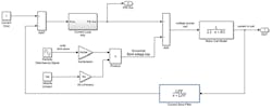
Figure 4 shows where the back emf loss is accounted for in relation to the current loop and a simplified RL motor model. The current loop’s job is to keep the desired current correct while any voltage disturbances are taking place. In this case, as the coil moves through the varying magnetic fields, there is a voltage disturbance, in the form of back emf (Bemf) that the current loop must correct for. In the block diagram, this is captured through at the sum block just before the coil model.
Figure 4: The back emf loss is accounted for in relation to the current loop and a simplified RL motor model.
The frequency of the voltage disturbance is critical. For slow speeds, the frequency is also slow, as the frequency is the linear speed in mm/sec divided by the magnetic pitch—mm/pole pair or electrical cycle.
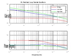
The units here become electrical cycles per second or Hz. At the low speeds and low frequencies, the loop gain is very high (Figure 5). In these regions, it may be difficult to see any benefit of optimal integrator tuning because the gain is so high that improvement may be in the noise of the measurement. At higher speeds and frequencies, however, maximizing I gain could lead to a significant improvement—two or three times—in current ripple from varying Kf.
Figure 5: Units become electrical cycles per second or Hz. At the low speeds and low frequencies, the loop gain is very high.
For this example, a 200 Hz sinusoidal signal was injected into the voltage summation block. The amplitude of the sine wave was set using a Ke value of 10 Volts per m/sec, at a speed of 0.5 m/sec and a variation of 10% of that value. What this means is that Kf or Ke will vary +/- 10% at a frequency of 200 Hz.
This is used to represent how a linear coil moves through a motor track with varying magnet strength. The varying Ke will cause a fluctuation at 200 Hz of the back emf component of coil voltage. This fluctuation will act as a disturbance to the voltage being applied to the coil. Figure 5 shows the two loop-transfer functions that were evaluated. Both have a 0 dB crossover frequency of approximately 2 KHz bandwidth but have different low-frequency gains due to the different I gain used.
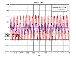
At 200 Hz, the gain difference is about 10 dB, which is a factor of three (3x). The net benefit of the 3x in gain is shown in Figure 6, where the higher Ki case is clearly performing better by about 2:1.
Figure 6: At 200 Hz, the gain difference is about 10 dB, which is a factor of three (3x).
Increasing low-frequency gain—Integrator gain—typically reduces phase margin of the servo loop. The amount of acceptable phase margin is not the same for every application. In mechanical systems, closing loops with 30° margin is common practice, while, in electrical engineering disciplines, such as operational-amplifier (op-amp) design, loops are closed with a minimum of 60° margin. The I gain optimization can become a very useful tool for the right application. The higher level takeaway from this discussion, however, is that, when tuning a control law to reject tonal frequencies, gain is what is important, not bandwidth. Two systems with the same bandwidth perform much differently against a tonal disturbance.
When servo terms are incorrectly bundled together, confusion can quickly occur. Here are some good examples of how “bandwidth” and “loop gain” can be used incorrectly.
- “The servo rate is 2 KHz.” In this example the user is mixing up two key elements of the servo loop—the servo sample rate and the servo bandwidth. These are two very different terms. The servo sample rate (Fs), sometimes called the update rate, is the rate at which the controller samples the feedback sensor and outputs a control action. Typical sample rate will vary between 1 and 10 KHz. As described previously, the servo bandwidth is the maximum frequency at which the control system will exert beneficial effort into a control system.
- “The motor resonance is 100 Hz.” Motors typically do not have resonant frequency, per se, but the servo loop does have a servo bandwidth frequency and is likely to have plant resonant frequencies. In this example it is not clear if 100 Hz is the bandwidth frequency or a plant resonant frequency. A clearer statement would be: “The servo bandwidth is 100 Hz,” or “The plant has its first resonance at 100 Hz.” The housing supporting the motor can have a resonant frequency. The back iron and magnet track for a linear motor can have a resonant frequency, and the coil for a linear motor can have resonant frequency. Typically, these resonances, or modes of vibration, are perpendicular to direct which force is created and are not strong contributors in the plant transfer function.
- “My servo loop bandwidth is 100 Hz, but I am not getting good attenuation of the disturbance frequency at 90 Hz.” In this case, the person has used the term “servo bandwidth” correctly but is incorrect in the expectation of how much disturbance rejection is achievable for a given servo bandwidth. Disturbance rejection, or tracking, is 100% dependent on loop gain; and loop gain near the bandwidth is typically low, so it is expected that limited performance will be achieved. The takeaway here is that bandwidth is not a good indicator of a servo loop’s ability to track or reject disturbances. Loop gain is a much more direct value to specify rejection or tracking performance. Bandwidth does tell how fast a servo can respond, but in most cases the speed of the response is limited by saturation of current or voltage.
- “Will the bandwidth double if I doubled the encoder resolution, going from 1 count = 0.5 μm to 1 count = 0.25 μm?” This is a commonly asked question, and the answer is no. The reason is that the maximum loop gain is always conserved and is limited by stability. This means that components within the loop can change their gains up or down, but stability rules govern the maximum loop gain. In this example, if the encoder gain doubles, another component within the loop must be cut in half to conserve the overall loop-gain value. Also, in this question, the user is mixing bandwidth and loop gain. Bandwidth goes up and down with a change in the overall loop gain, but the ratio is not necessarily 1:1. Loop gain is 1:1 with each of its components, so if the encoder gain were doubled, and no other changes made, the loop gain would also double.
- “If higher-resolution encoders do not provide higher bandwidth, what is the benefit?” The answer is repeatability, not to be confused with accuracy. The servo will move the load into position with +/- 1 count of error, assuming some amount of integral gain. The higher-resolution the encoder, the more precise the final position will be. In this case, accuracy is not improved with higher resolution because it is governed by the runout of the encoder scale markings and other factors, and not based on how the markings are interpolated.
ALSO READ: How to tune PID loops

Leaders relevant to this article:


