FPGAs Turbocharge Control Design
By Stuart McFarlane, Viewpoint Systems
A field-programmable gate array (FPGA) is a programmable logic device capable of supporting thousands of gates. Some engineers already use FPGAs to design controls. Others have heard of FPGAs but haven’t considered using them. Every so often, it’s good to look up from what you’re doing and see what’s going on. So, first question: Why use FPGAs in the first place?
FPGAs are fast. Today’s class of FPGAs can perform an incredible amount of processing and are capable of truly parallel processing, breaking the single processor serialization of execution. Algorithms running 10 MHz and higher are not unusual. Reaction times are measured in nanoseconds—plenty fast for today’s applications.
FPGAs are flexible. They can span the analog and digital world. The devices are especially good in the purely digital world, but if you add analog to digital and digital to analog converters, then you have a deterministic, high-performance mixed computing platform. The combination of functions incorporated into the fabric of the FPGA is up the control designer. Changes to the application can be downloaded to the FPGA without redesigning the circuit board.
My interest in FPGAs is not in the field-programmable feature, although that is very important. What I find more engaging is the flexibility and performance. For as long as control problems have been existed, the desire for higher performance has been constant. “If only the controller was faster, easier to program or more capable” is a common refrain. Every design is a trade-off of performance, manufacturing cost and development cost. What if the boundaries between those trade-offs were significantly redrawn?
Absorbing Functions
“We needed to employ a technology that could give us the performance we required in a maintainable package and a sensible price,” explains Martin Saxon, director, Product Technology Partners, Orwell, U.K. PTP develops custom control, test and measurement systems for research, development and production. “We required multi-channel data acquisition at 100k samples/sec synchronized with closed-loop hydraulic servo control on two axes, including safety checks, using up to 20 kHz loop rate. We required the capability to apply advanced control algorithms—non-linear multivariable adaptive and self-tuning control—as well as simple gain-scheduled PID control.” PTP’s aim is to use off-the-shelf hardware product wherever possible.
“When the design was carried out, we were not aware of any other single product that could provide the same capability as the FPGA product we used,” says Saxon. “We could have achieved the same goals using a combination of other products, but at extra cost and increased system complexity. We used National Instruments’ FPGA product so these claims are not necessarily applicable to starting from scratch with a bare FPGA and nothing else.”
For any given application, the electrical signal conditioning to connect the FPGA to the outside world still is required. However, you often can simplify the form of this conditioning. Components can be eliminated and their functions absorbed into the FPGA code. The designer can implement counters, pulse-width modulation (PWM) generators, signal generators, filters and math directly in the FPGA. For example, you can implement a complete closed-loop hydraulic actuator control with LDVT feedback with only two active external conditioning components—a voltage buffer for driving the LVDT excitation coil and a voltage-to-current driver for the hydraulic servo valve. The FPGA would provide the excitation waveform for the LVDT, demodulate the LDVT feedback to produce position, use position to compute velocity, implement the closed-loop model and output the command value to the servo valve. Add an analog pressure input and you can create a force controller with velocity-limiting or shutdown protection.
Programming Flexibility
“We need a time-critical process to generate accurate pulse-width modulation (PWM) signal,” explains Danny Hendrikx, process development engineer in R&D for Havells Sylvania’s Belgian lamp-making factory (www.havells-sylvania.com). “Also, our safety rules do not permit a regulated switch down that is driven by software when an emergency brake is triggered. I will always ride the safety procedures in the FPGA. Because an FPGA is hardware, and not software, it gives you a lot of flexibility according to safety matters. You can program a sequence-driven shutdown even when an emergency stop is triggered. Without FPGA, you would have a complex electronics device that still would have to communicate with the software, which would decrease the flexibility level.”
It’s analog input speed, not processor speed, that typically will limit control-loop rates. Instead of being at the mercy of external demodulation circuits, the feedback delay is tightly controlled and adjustable from theoretical minimum to any larger value.
Once this functionality is completed, you can add more integration. Is the position setpoint an analog or a digital communication protocol? It can be either or both. You can incorporate digital communication with relative ease. Is the relationship of the force linear or does it have a geometric relationship to another external signal?
The user can mix and match displacement sensors, LVDTs, RVDTs, resolvers, encoders, absolute encoders, SSI encoders, differential encoders and acoustic as required. It’s also possible to acquire temperature, resistance, voltage, current, force, pressure, flow, frequency and acceleration measurements and process them into other measurements such as RMS voltage, Watt meters, three-phase power and inductance.
If you don’t want to use the FPGA as the primary controller, but need it to act as a specialized co-processor, using the FPGA as slave device with a digital interface such as serial peripheral interface (SPI) bus would be completely normal. You could use the entire system described above as a slave to at PIC chip if required.
FPGAs excel at digital control. If your controller is mostly digital, dealing with solenoids, clutches, flags, encoders and proximity sensors like a paper or bag handler, the FPGA will give you very precise control over counting, electronic gearing, timing and complex relationships. Precise digital control of power supplies or brushless motors is a natural target for FPGAs. The parallel processing nature of an FPGA means that as the I/O count goes up, the performance doesn’t degrade. This leads to the next important use of FPGA in control design—simulation.
Securing Simulation
Once you’ve programmed your controller, even a conventional controller, and you’re ready to test or debug, do you really want to hook it up to your very-expensive machine? How about simulating the machine with another FPGA so you can test the logic, interrelationships and fault handling of your controller under controlled conditions? While simulations are never perfect, they will expose many fundamental issues without risking expensive equipment.
Modeling the device under control can be time-consuming, but the alternatives can be worse. Crashing a machine during testing is likely to be much more expensive than developing a simulation test bed. Fault injection is relatively easy with a simulator, as opposed to trying to create the equivalent fault in a real machine.
We developed a simulator for a customer who was developing a controller and had to show exhaustive testing of the controller but, for practical purposes, couldn’t perform the testing on the real machine.
The simulation consisted of receiving a solenoid command from the controller, waiting a short period of time, accelerating a simulated position until a velocity is reached, translating that simulated position into simulated pulse outputs corresponding to a gear-tooth proximity sensor and several other functions of the mechanical system as inputs and outputs of the controller. By adding specific fault cases such as low velocity or long propagations, the controller could be tested for conformance to its requirements without running a real machine. When the controller was attached to the real machine, the final integration testing went relatively smoothly. Changes to the controller were first verified on the simulator before being tested on the real machine.
An FPGA can simulate most real-world sensors and controls. The fidelity of the simulation is usually very good due to the speed of the FPGA. High-speed output of a signal with decent resolution will simulate analog signals for many purposes.
AS EASY AS LICKING A STAMP
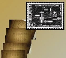
Figure 1: A postage stamp is used to demonstrate the surface size of the VLV test area.
Source: SPINX TECHNOLOGIES
You can implement specialized functions in parallel depending on requirements. For example, you might want to estimate the center of a pulse from a gear-tooth proximity sensor to evaluate vibration. Your correlation testing shows that simple threshold center doesn’t correlate, so you need a more exotic interpolated estimation of threshold time. This requires no hardware change, just a program change. Creation of specialized relationships between devices is one of the most important benefits of using FPGAs. When off-the-shelf components don’t have the functionality that your application requires, you can accomplish the goal often with improved results over the conventional approach.
Seeking Acceptance
Why aren’t more engineers using FPGAs for controls applications? They’re not easy to program and currently require specialized skills and time to achieve the desired performance. While the programming tools are improving, there are still vast opportunities for improvement.
“Change of mentality for a software programmer when dealing with an FPGA can be an obstacle,” warns Piero Zucchelli, chief scientific officer and founder of Spinx Technologies, Geneva, Switzerland. Spinx Technologies introduced a novel, software programmable lab-on-a-chip platform for the life sciences (Figure 1). “Even if the tool makes the transition very easy, the implementation behind it is far different. For example, the fewer the conditions, the faster it is, and the more parallel you design the workflow, the faster you are. Any conventional speed improvement solutions hardly work, and to know the actual performances of the individual VIs on the FPGA is a key to achieve good results.”
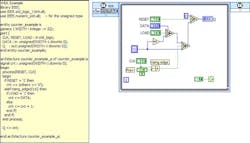
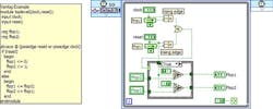
For most embedded applications of FPGA, the development tools are based on VHDL (Figure 2) or Verilog (Figure 3). FPGA vendors such as Xilinx offer different suites of development tools. Other tools like CoDeveloper from Impulse are targeted at programmers who are familiar with C.
VHDL ALTERNATIVE
Figure 2: LabView helps to create programming for FPGAs that eliminate the need to write code in VHDL.
Source: NATIONAL INSTRUMENTS
Personally, I use LabView FPGA to develop FPGA code for NI’s FPGA products. LabView is a graphical programming language that naturally supports parallelism, pipelining, 64-bit data and fixed-point math. LabView also supports Windows, embedded programming and FPGA coding within a common environment.
VERILOG’S EQUAL
Figure 3: Verilog is replaced with this LabView programming.
Source: NATIONAL INSTRUMENTS
“The LabView FPGA tool is simply unique,” agrees Zucchelli. “No other solution exists that can allow non-specialized engineers to develop fast-computational solutions. There’s no other solution allowing for a deterministic, 16-bit resolution to compute the angular position of our system 1 million times per second. Analog electronics would have suffered from calibrations and resolution, and software-based calculations would have missed the speed of processing by a factor of 1000x.”
Doing the Math
No matter what tools you’re going to use, you’re going to need to address the following challenges: training, coding, debugging, validation and reuse. Training can be either formal or informal, but you need to be proficient using the tools to make good progress on solving problems using FPGAs.
Coding, debugging and validation are all part of the same process, but the tools you use may make each one of these items easy, hard or extremely difficult. One of the biggest challenges to coding applications that are more than simple logic and integer math is dealing with engineering units. The two most common approaches are pre-scaled integer values and fixed-point math. They are related concepts, but in the first case the programmer must keep track of the resolutions and implied scale factors, resulting in code that is often difficult to follow and debug. If you have fixed-point math functions to work with, the code is more legible and easier to conceptualize. You still have to worry about overflows, underflows and ranges, but I much prefer fixed-point algorithms to scaled integer functions.
A case in point would be an encoder that has 10,000 lines/in. and an analog displacement that has a range of ±2 in. and a resolution of 16 bits (1 part in 65,536). The bit weight of each number is different. If you want to subtract one from the other and have a meaningful result, they need to have the same implied decimal point, or you can use fixed-point math. Multiply the encoder value by ~1.638 and you have a number that has the same bit weight and implied decimal point. This is straightforward in fixed-point math. Just multiply the encoder count by .0001 [32,-12]. The notation [32,-12] notes a 32-bit fixed-point number with -12 digits of integer. For integer math, (count * 107374) >>16, where 107374 is (32768/20000)*216.
“There are a few downsides on programming FPGAs because we are used to working in a flexible Windows environment,” warns Hendrikx. “You have to compile the program. This can take a while depending on the program size. You cannot debug it with breakpoints and markers because it is a compiled program, and you have to respect the 32-bit compilation when using numbers. This can give you some problems with calculations.”
Saxon has similar warnings about the math. “FPGA programming is rather different from configuring an off-the-shelf servo-hydraulic controller,” he explains. “The starting point is a blank sheet, and it takes time to develop the application framework, although there are an increasing number of building blocks available to help. For the programmer, the difficulties stem mainly in the constraints of fixed-point math; floating point arithmetic is not available. So the implementation of complex algorithms can require very significant design effort to ensure accuracy.”
Once you figure out the coding as above, how do you debug and test the code to prove that the results are as you expect them? For me, the LabView platform allows the algorithms to be tested and verified before being committed to the FPGA. Complex functions like RMS, filters and integration can be verified before use, instead of trying to diagnose the cause of unexpected results later in the process.
Once you have invested in the whole process, future applications and modifications are made easier if you have designed your components for reuse along the way. IP cores, or IP blocks, can be purchases and included into your application for many different functions. Even if you don’t purchase IP cores, you should be thinking of developing internal IP cores for your organization so that you don’t find yourself reinventing the wheel over and over. We have continued to collect, organize and publish IP cores for internal use over time so that each subsequent application can be developed more rapidly than the one before.
“We consider the cost-effectiveness of particular solution architectures on a case-by-case basis,” says Saxon. “The FPGA solution has considerable benefits for certain applications in terms of capability, maintainability and price. However, this is not universally true, and there are many other projects for which we continue to use more traditional servo control and data acquisition products.”
As FPGA technology and hybrid processor/FGPA technology become more widespread, the impact on control design will be extremely significant. Reduction in component count, flexibility, reduction in design cycles and improved performance all will be economic drivers for future control design. Those companies that are positioned to take advantage of this technology will have a definite competitive advantage over those that don’t.
Stu Mcfarlane is vice president at Viewpoint Systems, a system integrator in Rochester, N.Y.


