Implementation of Wireless Networks Takes Time and Patience
By Alice McWilliams, PE, Chevron Phillips
The application of new technologies seldom goes as planned and can be an outright adventure. But the potential for significant cost savings can make overcoming the hazards and pitfalls well worth the journey.
That was the case at our plastics plant in Pasadena, Texas, where we needed to overcome obstacles and create a wireless system to monitor certain data readings.
Initially, the impetus for the project involved the need to obtain two readings, but things escalated quickly. The equipment was installed in August 2007. Design for the installation had started earlier, in February.
The Application: a Wireless Opportunity
We have a 40-ft-tall API tank used when we unload a barge. Each time, the operator would climb the tank to record temperature at the vent and vent valve position after the tank's condenser unit. The plant wanted to automate the recording of measurements to record the vent temperature and vent valve position to provide improved documentation for our environmental records and improve operator efficiency by eliminating the time-consuming, lengthy, repeated trek to the top of the tank (Figure 1).
Figure 1: Eliminating the time-consuming, repeated trek to the top of the tank with a wired measurement solution would have required a 40-ft-tall scaffold to run the conduit and cable.
Source: CHEVRONPHILLIPS
Because the process variables we wanted to measure were at the very top of this tank, it would have required a long cable and conduit run up the side of the tank. It would have required a 40-ft-tall scaffold to run the conduit and cable. The costs to obtain just two new readings did'nt seem justified compared to a traditional hardwired method.
"We began to look at a wired solution," says John Scott, senior account manager from the Rosemount division at Emerson Process Management (www.emersonprocess.com), "but we came up with a 65% installation savings by going wireless. One of the bigger costs for a wired solution would have been the scaffolding.”
Wireless obviously was the best choice. We looked at several wireless network solutions but determined that Emerson was a good choice for this plant. Regular-style wired Rosemount transmitters already were used at this unit. Training on the handheld was up-to-date. This meant that training only needed to cover troubleshooting changes due to the wireless hardware and setup. This would minimize our training costs, as well.
Wireless Network Design
We began to seriously explore implementing a wireless solution to this problem. One concern was how to provide valve position. Emerson didn't offer any direct valve-positioning transmitters except as an add-on to the digital valve positioner. The controller for tank pressure was a local pneumatic controller with a pneumatic valve positioner. I eventually realized that I could use a pressure transmitter on the controller output and provide an implied valve position.
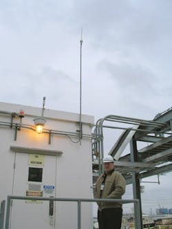
Designing a wireless network, to my interpretation, meant that cable runs were kept to a minimum, reducing both installation and material costs. It seemed, therefore, that the best location for the wireless gateway would naturally be on top of the rack room (Figure 2). I could easily interface with the old Provox DCS equipment via the intelligent device interface module set to accept Modbus and run only three short cables—Modbus, Ethernet and power—to the roof.
Figure 2: The gateway on the rack-room roof was difficult to access, which was discovered when the first gateway developed mold on an electrical card before the network was even launched in August 2007.
Source: CHEVRONPHILLIPS
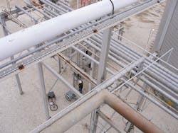
This older version of the wireless network required that the distance to the gateway be less than 500 ft. The temperature and valve-position-measurement points were 600 ft away from the rack room. Additional transmitters between the API tank and the rack room were needed to act as repeaters for the API tank data. These additional wireless applications between the API tank and the rack room would improve both distance and stability needs. Mesh wireless networks also become more stable as the number of nodes to the network increases. Fortunately, it was easy to find more readings that the plant wanted. The production engineers for our unit also were excited about trying a wireless network. Two additional measurement applications, the bearing temperatures for two pumps and the barge unloading line pressure, fell into our laps (Figure 3).
Figure 3: Additional transmitters were needed to act as repeaters. Mesh wireless networks also become more stable as the number of nodes to the network increases.
Source: CHEVRONPHILLIPS
One of the pumps on a tank closer to the rack room had experienced bearing failure earlier that year and caused a hydrocarbon leak into the electrical housing. Monitoring the pump bearing temperature would improve reliability and safety in this operation.
Also, our barge unloading line was experiencing pressure excursions in excess of what we would like. It was not easy for the production engineer to tie the higher pressures with specific events during the unloading cycle. Most of the unloading valves were hand-operated, and the barge unloading information also was isolated to the dock area. The recorded pressure indication could help determine the point in the cycle when the high pressure occurred so we could develop better procedures for preventing recurrence. Both of these applications were a great opportunity to bring information that would provide improved plant operation to the DCS. In the end, we planned to develop a wireless network consisting of five transmitters: tank vent temperature, vent valve position, two pump-bearing temperatures and barge unloading line pressure.
Transmitter Update-Time Decisions
Wireless transmitters don't provide data on a very fast update rate. Emerson generally recommends update times around a minute. Pressure is a fast-changing variable and I was particularly concerned about the slow update rate for the two pressure transmitters on the unloading line. What if, at a 1-min update rate, we totally missed recording the event that signaled the pressure excursions on the unloading line?
In the end, I picked 15-sec update rates for all the transmitters except the barge unloading pressure. I found out at installation time that, although the recommended lower limit was 15 sec, the system actually could perform at much faster rates. I selected a 3-sec update rate for the barge unloading line pressure. The down side to changing to a faster update rate was sacrificing some battery life and gateway capability.
Transmitter Variables
These days you can pick and choose what you feel is important information from your transmitters and bring this data into the DCS. I heard and read a lot about battery life and battery voltage from Emerson's experts and literature. I decided that, besides the main transmitter variables, I also would bring in the battery voltage as an additional variable for each transmitter. This turned out to be a good decision. Now I regularly review the battery voltages, and we created an alarm to alert the operator when the voltage dropped too low.
What About Radio Interference?
For the installation of a wireless network, another hurdle needed to be cleared. Our plant radios use the same 900 MHz frequency range as the network. The radios provide critical communication for our operators, especially if an abnormal situation should develop in the plant. Our radio group was very concerned about a network that would run at the same frequency as the plant radio system.
We held two separate in-plant trials using Emerson sales-demo units. During the second trial, the radio group brought its frequency analyzer. It showed no interference. However, they still were not completely comfortable and wanted us to wait until the 2.4 GHz wireless transmitter network was available. To put their minds at ease, Emerson's Scott explained five key aspects employed by the network security, including protection/encryption, authentication, verification, key management and anti-jamming. That satisfied their concerns.
Mind the Details
By July 2007, I was reviewing the installation by our on-site construction team. At this point I realized that none of the transmitters had batteries installed. Apparently, the batteries were delivered separately and without a specific line on the purchase order (PO). The receiving department didn't have the means to handle a delivery that didn't match to the PO. All the new batteries were lost and never located. The planned imminent installation by the Emerson team was delayed several weeks while the batteries were reordered and delivered.
Gateway Troubles
Since the gateway and antenna were married together, I thought putting the gateway on top of the rack room to receive signals from all different directions within the plant would be a good idea. Unfortunately, the roof was difficult to access. We discovered how inconvenient a location this was when the first gateway developed mold on an electrical card before the network was even launched in August 2007. Emerson replaced the gateway under warranty. The second gateway quit in November 2007, a little more than two months after it was installed.
Then, one day all the points started drawing straight lines. I had five or six irons in the fire that day. So, rather than call Emerson tech support, I cycled power in the hope of resetting it. Due to the lack of any luck at all, that action vaporized all stored data on what had gone wrong with the gateway. The failure of this gateway, after post-mortem analysis, again pointed to the radio card. Emerson again replaced the gateway under warranty and lent its demo unit to us until the warranty replacement gateway arrived.
[pullquote]When the third gateway came, it included a remote antenna. This was a feature I had wanted from the start, but it only recently had become available. Getting the gateway down from the roof and adding the antenna made a huge difference in troubleshooting accessibility. Finally, the wireless gateway with remote antenna was installed and operational. It seemed things were looking up.
Wireless Mysteries
The temperature transmitter on the very top of the API tank—the sought-after measurement that started this grand adventure—was the first one to give me trouble. One lovely day in December 2007, the outside temperature was 70 °F. The next day the temperature plummeted to 35 °F. This transmitter provides the condenser temperature reading that was the cornerstone of the whole wireless network project. Examining trends of the battery voltage showed 6.84 Vdc on Dec. 15 and 5.56 Vdc on Dec. 16. Somewhere around 5.5 Vdc is the point at which the transmitter stops functioning.
I was very surprised to have a battery failure after only four months of operation. From what I had discerned from the vendor literature, I expected these batteries to last for years. I hadn't expected to need spares so soon.
Emerson brought a replacement battery, and soon we were back in operation, but I continued to be puzzled by the battery failure. Obviously, these batteries developed lower voltages in the colder weather. I tried without success to procure some sort of graph or formulas to determine battery life. Battery life apparently was meant to remain a mystery to all users.
Mysteries continued with a new slant. My important API tank condenser temperature transmitter suddenly stopped transmitting on March 6, 2008. Sixteen hours later, before I could even determine that it had gone nonfunctional, the transmitter resumed sending data. Did something get in the way of the radio signal and break the path?
The condenser transmitter had two communication paths to the gateway: one directly to the gateway (600 ft) and another relayed through the valve-position pressure transmitter (5 ft away). This transmitter was on top of a 40-ft tank and the pressure transmitter that it communicated with most reliably continued transmission of its data throughout this episode. Battery voltage was not an issue. The voltage when the device quit communicating was 7.08 Vdc. Emerson performed an on-site mapping of the wireless network system operation through the 1420 Gateway. However, this offered no clues to what caused this mysterious signal loss. This same event occurred on this condenser temperature transmitter later in 2008. This time, the transmitter was rebooted to start communicating by pulling out the battery and putting it back.
I again contacted Emerson to glean some additional insight into why this transmitter would lose contact with the wireless network. They offered to repeat the system mapping that had been done earlier. I declined the offer since it required taking the whole network down for an hour or so and the process had yielded nothing to help previously. They did suggest trying the antenna on the transmitter at a different angle. We implemented this suggestion, and the condenser temperature transmitter has remained in communication since that date.
Trouble When Wet
The batteries, however, were not done plaguing me. On April 28, 2008, one of the pump-bearing temperature-transmitter batteries dropped to 5.37 Vdc during an ambient temperature swing of approximately 20 °F down to 58 °F, the point at which the transmitter failed high. This battery was replaced after a life of about one year.
I was confused. Where were the years of battery life that the literature talked about? At the Emerson Conference in October 2008, I discussed battery life with any Emerson expert who would listen. One of these experts told me that one year really was what might be expected with an update time of every 15 sec. I keep looking for that chart where I can calculate battery life myself.
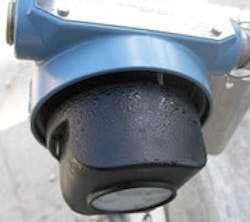
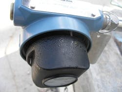
At one point, given our concern about why transmitters were losing signals and batteries, we removed the transmitters' covers and found some of them had condensation on the batteries. The first thought was: "Wow. This is the source of our problems." The recommendation was to put Teflon tape on the conduit plugs to discourage any outside air exchange with Houston's humid weather (Figure 4). Little details often make the difference. However, it's difficult to prove whether this made a big difference in our battery life because this pump bearing temperature transmitter is not done with me yet. It failed again on May 18 and again a month after that. It turns out this was a good transmitter gone bad—a transmitter that ate batteries. Emerson provided a replacement under warranty, and there have been no failures since.
Figure 4: Houston’s humid weather caused water to accumulate beneath the transmitters’ covers, which warranted Teflon tape on the conduit plugs to discourage outside air exchange.
Source: CHEVRONPHILLIPS
Adventure Lessons Learned
With all of these lessons came valuable experience. We developed troubleshooting experience in wireless. Plus, we added the temperature transmitter ourselves, without Rosemount, to prove the system is easy to maintain and grow. We also got a lot of valuable process information at a much lower cost due to the 65% installation savings. The barge-unloading pressure did provide the information needed to determine improved operation practices. And when Hurricane Ike hit in September 2008, the network kept running without a hitch right through all that extreme wind and rain.
Alice McWilliams, PE, is senior instrument and controls engineer at Chevron Phillips (www.cpchem.com) in Pasadena, Texas.


