The Not-So-Odd Couple
Some important properties and characteristics of electric motors and electric generators can be demonstrated easily using an actual motor and generator. Grade or middle school students could conduct these experiments. Through my own experience, I’ve observed that these experiments, executed on a laboratory table, can be very useful as a teaching tool.
Basically Speaking
Motors come in all shapes and sizes and most often are used to convert electrical energy into mechanical energy via the rotation of a shaft. Since the primary electric source in a home is single-phase, 110 Vac, the motors that drive a washing machine, vacuum cleaner, all other gadgets and tools are designed for that supply. For simplicity and reduced control circuits, many of these household motors turn only in one direction.
In your automobile, there are many motors of different power levels that run on 12 Vdc. The starter is by far the strongest electric motor in a conventional automobile.
Industrial applications often require much higher mechanical outputs than the typical appliance or car electric motors and thus use motors that are much larger in size and are designed for higher DC voltages or multi-phase AC voltages. In addition, these motors also have a much higher current rating.
Generators usually are not found in a household. Some houses have an emergency generator, in case of loss of electric power.
Every automobile has a generator to provide electric energy for ignition, various fans, accessories and lights, as well as to recharge the battery.
I used to ride a bicycle with a small generator attached to the frame. At night, this human-powered generator could be leaned against a wheel to produce electric energy for the headlight and the taillight.
On the whole, most generators are big and used to supply the power grid with electric energy. It takes a lot of mechanical power to crank the shafts of these generators. Mechanical power is obtained in steam power plants from coal, gas and nuclear sources, with diesel engines or hydro turbines, or more recently with wind turbines erected on hilltops, often in groups as windmill farms.
Basic Motor Designs
Motors are based on the principle that opposite polarity magnets attract each other, while magnets of the same polarity repel each other. One magnet is located on the stator and one magnet is on the rotor. If those magnets are not lined up, the rotor will turn until they do. Once the magnets are lined up, rotation stops.
One of these magnets could be a permanent magnet—a rare-earth magnet—or a quasi-permanent magnet—an electromagnet with coil windings driven by a DC current. The other magnet is an electro-magnet, the orientation of which is modified continuously. As a result the rotor keeps trying to line itself up. If this magnet modification is done in an intelligent way, such as in a rotation to the right, then the rotor will rotate to the right.
DC Motors
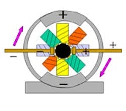
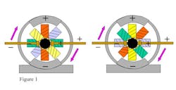
To sustain rotation, and since the permanent magnet cannot be reoriented, the electromagnets must be activated or deactivated. In a typical DC motor (Figure 1), the stator has the fixed, permanent magnet and the rotor is composed of a number of windings.
Basically one or two windings are activated at a time via commutation, depending on the number of coils on the rotor. At start-up, referring back to Figure 1, the green winding is activated. With the polarity shown, the rotor will turn clockwise, trying to align the green magnet with the stator magnet. As the rotor turns, the blue coil becomes activated, while the green coil is deactivated, and so on as shown after first commutation. The rotor field is reoriented in discrete steps, according to the number of rotor windings, while the rotor turns. Details about pole shaping and arrangement of air gaps are not shown. The rotor could have many more individual windings, and for that reason, two or three adjacent windings could make contact through commutation at any one time.
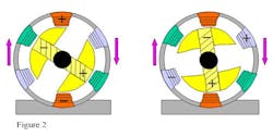
In another form called a brushless DC motor or an inside-out DC motor (Figure 2), the permanent magnet is on the rotor. This magnet again can be a rare-earth magnet or a fixed electromagnet connected via slip rings. External solid-state switches turn on the proper stator winding as a function of the rotor orientation. The commutation that took place on the rotor in the previous example takes place in the stator windings.
When, the red stator coil in Figure 2 is turned on, the rotor moves clockwise trying to align the opposite poles. At that time commutation moves to the blue coil and then to the green coil and so on. At nominal speeds, the excitation moves from one phase to the other, turning on and off the different stator coils. At standstill and low speeds, the active stator phase is not a pure DC signal but a pulsed DC signal to avoid saturation. For higher power systems an almost perfect three-phase excitation is created through solid-state switches.
Synchronous Motors
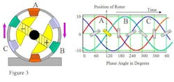
A synchronous motor is basically the AC equivalent to the brushless DC motor just discussed. In these motors, the rotor turns at the same speed as the outside field. In general, the outside field for a synchronous motor is a three-phase, sinusoidal excitation obtained from the three-phase, 60 Hz line. When no mechanical load is connected to the motor, the rotor is lined up almost exactly with the stator field (Figure 3). As the mechanical load increases, the rotor lags the stator field by several degrees but is still in step with the field. If the load is increased beyond the rated value, the rotor will fall out of synch and come to a halt.
With a moderate load applied, the rotor follows behind the stator field by several degrees. If the load increases the lag increases and vice versa. A synchronous motor cannot be started from standstill by simply turning on the three-phase AC. These motors need to be brought up to speed by auxiliary means before they can be connected to the line. Then they turn synchronously with the three phases no matter what the torque.
Induction Motor
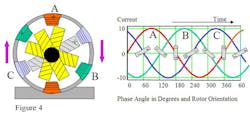
At first glance, an induction motor (Figure 4) looks like a combination of the DC motor (Figure 1) and the synchronous motor (Figure 3). It has many rotor windings, similar to the DC motor, but they are not connected to any external source or commutation. These are many individual short-circuit windings positioned in different orientations.
If a fluctuating stator field is applied, the changing magnetic flux induces a current in at least one of the rotor windings and thus creates a rotor magnet of opposite polarity in that plane. At the same time, the current in the other stator windings—60º and 120º offset to the rotor magnet—produces strong stator magnets. As with the DC motor, the rotor now rotates to align. After a 60º turn of the rotor, the stator excitations also have changed by 60º. The new stator field now excites the rotor winding again and the strong stator magnets now appear 60º turned. Note that the rotor magnet is reestablished through induction when the current in the stator changes most rapidly at zero crossings of the stator current.
For quantitative descriptions, equations and performance of different motors see The Industrial Electronics Handbook, Editor-in-Chief J. David Irwin, CRC Press and IEEE Press, 1997; ISBN0-8493-8343-9, Chapter 13. Dr. Dummermuth also is a contributor to chapter 41 of this reference. |
The condition described here is under no load. Under load, induction motors turn more slowly than the driving stator field. This speed loss is called the slip. When slip occurs the rotor basically falls one rotor-winding back and continues to fall further back over time. Slip increases with load. If the load is excessive, the rotor will drop out and come to a halt. Because of that slip, however, induction motors can start from standstill by just connecting the stator excitation.
In the gray rotor coil in the illustrated induction motor, the current in C changes rapidly, going through zero. The rotor magnet is established in the gray coil through induction. At that time A is positive, Not A is negative, B is negative and Not B is positive. We can see readily that the rotor will move clockwise and follow the rotor movement and the corresponding stator fields along the time line.
Many applications use the three-phase, 60 Hz line directly, but advances in solid-state power switches made it possible to create three-phase quasi-sinusoidal phases at virtually any frequency. The incoming AC is rectified and a DC voltage is created. This DC is switched in a sophisticated sequence into the three-phase windings. Control circuits are called variable-frequency inverters or solid-state drives because the primary applications are servo drives.
Since the rotor slips, very-accurate position and velocity feedback are needed to properly control the artificial phase generation. Control is difficult at low speeds; at standstill it becomes tricky. Actually two rotating excitations with equal strength are overlapping each other; one rotates left and one rotates right. When a command is given to move right, the strength of the left excitation is diminished and the strength of the right one increased. Eventually the left one disappears completely once the motor is on its way.
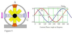
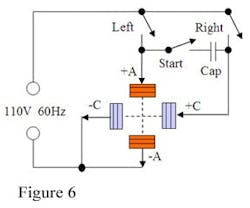
Low-power induction motors can be driven from a single-phase source (Figure 5). However, the single phase is not sufficient to get the motor started from a standstill. An auxiliary phase is required. A capacitor is connected to the primary phase to create the auxiliary phase, 90º ahead of the primary. This creates a rotating field. Once the rotor reaches its rated speed, the auxiliary phase can be disconnected.
Observing the gray rotor coil, the current in C changes rapidly, going through zero. The rotor magnet is established in the gray coil through induction. At that time A is positive and Not A is negative. It is seen readily that the rotor will move counterclockwise. After 90º, C is negative and Not C is positive. At the same time the current in A changes rapidly and reestablishes the rotor magnet. A circuit diagram (Figure 6) shows the connections for a single-phase induction motor.
Generators
The DC motors of figures 1 and 2 already have been presented as DC generators. Indeed, there is some current ripple as commutation takes place. This is true for both motor and generator.
The synchronous motor of Figure 3 needs no modification to run as a generator. In motor mode, current flows from the source into the stator windings and the rotor lags behind. If the rotor is driven by an external force, such as a turbine, to overtake the outside rotating field, then current flows from the windings back to the source and the rotor now leads the rotating field. This is the primary mode of electric power generation.
Figure 3 with just one set of stator windings is the bicycle generator mentioned earlier. Just connect the headlight and taillight in parallel as loads to the stator winding. The frequency and the voltage of this AC increase with the bike speed, and so does the brightness. At standstill, no power is generated, so the lights are off. Be careful while you wait at a traffic light.
Because it has no magnetic field of its own and because it slips with varying loads, the induction motor of Figure 4 is not typically used as a generator. It still has the same properties, however, and certainly develops a back-electromotive force. Running in idle, this back-EMF is nearly as large as the driving voltage. Under load, turning slower, the back-EMF is reduced and the motor consumes more current. In a stalled condition, like the DC motor, it draws very large current.
Dr. Ernst Dummermuth is a consultant in process control, motion control, automation and intellectual property. He has been involved in advanced technology endeavors including architecture proposals, fast prototyping, concept verification, standardization and product development. His work has yielded 46 patents and dozens of publications. You can reach him at [email protected].
THE MOTOR EXPERIMENT
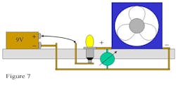
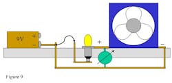
Many computers and small electronic equipment use small DC fans for cooling. The nameplate might indicate 12 Vdc with a current rating of 0.5 A. For this demo, I used a Comair-Rotron Model MD12B1 brushless DC motor as shown in Figure 2. Next get a 9 V alkaline battery with a snap-on connector for easy battery exchange, an alligator clip, a flashlight bulb PR3—normally used for three D size batteries—and some copper wire. You also need a small soldering iron and solder to make connections.
Mount the fan, battery and flashlight bulb on a piece of plywood. Drill a hole to stick the lightbulb into the plywood, and drill as many smaller holes as needed to run wires from top to bottom, for conductors or for fastening of equipment (Figure 7).
The motor behavior can be observed under all load conditions—stalled, start-up, some load, no load—by simply controlling the movement of the fan with your hand. These are the same characteristics present in high-power motors, but here we see and feel them more readily.
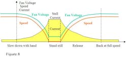
Notice the relationship between the current through the motor which is indicated by the brightness of the bulb, the voltage on the motor and its speed for various operating conditions (Figure 8). The fan voltage can be measured with a voltmeter.
A high stall current, or startup current, is typical for motors. At start-up, the bulb shines brightly and then dims while the current decreases until full speed is reached and just a weak glow remains. The voltage across the fan increases with speed. This voltage is the back-electromotive force. Because the fan is turning, it becomes its own little generator, generating a voltage that opposes the 9 V battery, and in the experiment at full speed, it was measured at about 7.0 V, with the battery itself holding at 7.7 V.
Indeed, every motor generates this back-EMF while rotating. The back-EMF opposes the current flow into the motor. It is actually a smaller current back out of the motor in the opposite direction. So every motor is a built-in generator. If this fan is forcefully made to rotate even faster, then the opposing back-EMF voltage may eventually exceed the battery level and the battery will begin to recharge.
A strong hair dryer can help to verify this behavior. If air is blown into our experiment fan to help it rotate faster, the light bulb completely darkens, and the back-EMF is increased. If air is blown from the other side to slow down the fan, the lightbulb gets brighter since the back-EMF is now reduced because of increased load.
The generator capability can be demonstrated (Figure 9) with the battery removed from the circuit. Using the hair dryer, blow air into the fan, making it spin backward. Once the fan turns fast enough, the lightbulb will glow since the fan is generating power. Generally, blowing from either side will work, but this particular fan motor is polarity-protected, so only one direction works.
MORE ARTICLES BY ERNST DUMMERMUTH AT CONTROLDESIGN.COM
- Dr. Dummermuth has contributed several worthwhile stories to CONTROL DESIGN during the past few years.
- Autonomous Cooperating Agents, In a rod mill, multiple cooling functions coordinate efforts to achieve an overall performance characteristic.
- Warm and Fuzzy, In Fuzzy logic can extend traditional binary logic. A heater control application demonstrates the method.
- Algebraic Solution Beats Fuzzy Logic. A non-linear, tunable PI controller provides improved performance in applications that need closed-loop control response.
- Closed-Loop PID Algorithms in Motion. Differential feed forward can be used for numerical controls, or integral feed backward can be used for trajectory control of motion.
How helpful do you find refreshers and primers on engineering topics? Do back-to-basics articles provide you with the kind of information that helps you to perform better as a controls engineer? Which topics would you find helpful? Sound off.
