Jim Montague is the executive editor for Control. Email him at [email protected].
It’s all about the layers. Whether you’re making dipped candles, Samurai swords, or concrete pipes, properly applied layers make pastries delicate and folded steel and molded concrete stronger.
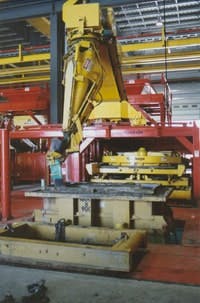
Hawkeye Group and its Hawkeye Concrete Products division have been making vibration-under-pressure (VUP) machines in Mediapolis, Iowa, for more than 50 years. Its users can mold up to 12-ft diameter concrete pipe and box sections for sewers and culverts. Consisting of a central hopper, conveyor, and chute feeder, VUPs fill a form and then vibrate it. This liquefies the concrete and allows it to fill, compact, and precisely match every crevice of a form (Figure 1). This is similar to the liquification that can occur during an earthquake, when the ground vibrates, allowing it to sometimes flow like a liquid.
Shake It Up, Baby
Hawkeye’s VUP machines fill forms with concrete, vibrate them to compact the material, and turn out up to 12-ft diameter pipe and box sections.
Photograph courtesy of Hawkeye Group
Depending on design and specification variances, Hawkeye’s VUP takes about 20 minutes to fill a form. These forms can be as wide as 12 ft sections or as small as 4x6 ft box culverts. Once compacted, the resulting concrete sections can stand unsupported, and usually cure overnight. One VUP machine typically makes 15-20 pieces per day.
VUPs initially employed manual hydraulic levers and valves, which required operators to manually follow outlines and fill the shapes being molded. Then, about 15 years ago, Hawkeye updated its molding machines with PLCs and other automation components, which allowed users to hit a button, and let the machine track assigned shapes on its own. These previous VUPs included GE Fanuc’s 90-30 PLCs and Hawkeye’s proprietary software algorithms to run AC vector-drive motors, typically a 3-hp motor for radical functions such as main feeder pivoting and a 1-hp motor for the chute. Relatively low-horsepower motors can be used on the feeder and chute because they perform spinning functions that don’t need to overcome too much gravity, though they do need to cope with high levels of inertia.
PLC Speed Limits
Despite the benefits PLCs and electric motor drives provided, there still were some persistent drawbacks. While the PLC computed coordinate points for the motion, and drives moved the hopper and chute pivot axes, this system sometimes couldn’t handle the VUPs often heavy and varying concrete loads. The feeder mechanism alone can weigh up to 10 tons when full. When burdened with especially heavy loads, the electric motor drives would trip and shut down due to overloading. Though these stoppages happened only once or twice per day on average and it only took a couple of minutes to reset the machine, they could be problematic for users trying to produce products quickly. The system also couldn’t achieve some desired motions while staying within the motor power curve.
In addition, while the former PLC’s approximately 30-msec cycle time was relatively fast, it wasn’t quick enough to track points around the form in time to make concrete layers thinner than the usual 6 in. This was a drag on Hawkeye’s goal of reducing machine processing time without increasing its costs.
Hopper and Chute
The VUP machine’s hopper and chute must handle widely varying weights of concrete as they move hydraulically about pivot points to fill the molds.
Photograph courtesy of Hawkeye Group
Reconsidering Hydraulics
During the VUP’s most recent revamp, Hawkeye was approached by long-time collaborator Jack May of Iowa Fluid Power, who proposed replacing the machine’s electric drives with a two-axis, electro-hydraulic motion controller with Profibus communication capability from Delta Computer Systems. Because the motion controller can calculate complex motion paths using its internal software, Hawkeye was able to switch VUP from its former high-performance PLC to a lower-cost PLC with more moderate, but adequate, performance. The motor on VUP’s conveyor already uses hydraulics. Delta was chosen because it already aids hydraulics on Hawkeye’s other machines.
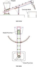
To make the chute’s end follow the mold’s shape, RMC70 directs the two rotational axes to follow profiles defined by user-developed mathematical formulas. Besides shaped boxes and round pipes, elliptical and arch-shaped pipes can be formed with the appropriate motion profile programs. The system incorporates an operator interface that provides key X-Y coordinates to a PLC, which passes them to the motion controller. The PLC also handles operation of the transfer belt and other control functions. The motion controller calculates additional points to complete the shape being poured, and then calculates the main pivot angle and chute angle needed to hit each point. Then the motion controller moves the axes to trace the path, and the hopper and chute move hydraulically about the pivot points to fill the molds (Figure 2).
Though electric motors are usually thought of as easier to control than hydraulics, which historically have more widely varying fluctuations when operating, Hawkeye found that RMC70 could work with the hydraulic system it designed and built using Rexroth’s hydraulic valves and other components from IFP, allowing it to trade its former electric motor for a hydraulic motor like the one already in its conveyor. Delta’s motion controller takes feedback from the hydraulics via a quadrature encoder mounted on each rotational axis, and calculates cycle loops in 2 msec to smooth any fluctuations. Because its new hydraulics are more forgiving when handling heavy loads and overloads, VUP could now move these widely varying loads smoothly and precisely.
“One problem we have is that concrete gets plugged in the chute, and this can cause vastly different loads on the motor from 1,000 to 3,000 lb,” says Ben Schmidgall, Hawkeye’s engineer. “We’re trying to solve that one by using a bigger hydraulic motor for low-speed control. It’s still in development, but the hydraulics should be a good investment because its controller costs somewhat less, it calculates way faster than a PLC, and we’ve had no trip problems.”
Faster Math = Faster Forming
Before programming the motion controller with the complex mathematics needed to track Hawkeye’s concrete forms, Schmidgall tested these numerical methods by using Delta’s simulator embedded in its motion control software. He generated sample points for the moves and then watched the simulator graph out the target and actual positions. He started by tracking simple shapes, and then added features. To track the motion around a square, for example, Schmidgall started with a consistent linear speed, and then slowed down the motion near the corners of the box, still just using the simulator. Though he’d never done complex motion control programming before, Schmidgall says he simulated all of the system’s motions onscreen. Once he got the machine and motion controller hooked up on the plant floor, it only needed to be tuned.
Plotting Motion
A motion plot shows axis position and velocity on the vertical scale versus time on the horizontal scale. The black line shows target chute axis position; green is actual position; gray is target chute velocity; and yellow/brown is actual velocity. Remaining lines depict radial axis, which is moving only slightly. When the motion system is tuned correctly, the plot lines showing actual position and velocity overlay the plots of the target values.
Photograph courtesy of Hawkeye Group
“The machine’s PLC previously had to make all the required adjustments, but now it just tells the Delta motion controller that the machine needs to make a 10x6 ft box,” says Schmigdall. “Then the controller’s software connects 64 dot points and does the trigonometry to figure out the angles and timing to get the machine into the right positions at the right speed. One of the motion controller’s main advantages is its simulation and graphing ability. Using our old system, I had no way of monitoring the machine’s motion, so there was no way to tell if it was tuned precisely. Now, not only was I able to know when the system was well-tuned, but I could use the system graphs to show my progress with the project (Figure 3).” In addition, Hawkeye’s new system has a modem for remote programming and maintenance, which Schmidgall or other users can access to diagnose system problems remotely or do fine tuning.
“Most importantly, calculating cycle times faster means we can track box forms faster, and this allows us to make layers as thin as 3 in., which we can fill, vibrate, and compact twice, and still do it more quickly than one 6-in. layer,” says Schmidgall. “Despite the variance in the different forms we’re filling, I think we’re operating about 10% faster overall, and the thinner layer also means we’re making better quality concrete.”
Schmidgall adds that he and Hawkeye learned several lessons from their VUP upgrade project. First, hydraulics can perform more effectively than electric motors when heavy loads must be precisely positioned. Second, simulating motion and related requirements before building a machine system can shorten development time. And third, using control system modules tailored to specific tasks, such as electro-hyrdaulic motions controllers with math capabilities, delivers the greatest functonality and value.
About the Author
Jim Montague
Executive Editor, Control
Jim Montague is executive editor of Control. He can be contacted at [email protected].

Leaders relevant to this article:


