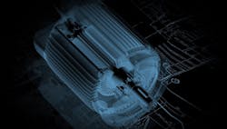
The driving force behind most automation starts with a motor. Now the more challenging readers might be thinking, “not if it is air.” Well, one might confidently argue that even air needs a motor to get it in motion. After all, air and hydraulic systems need a motor to drive the pump to give force to the medium.
Motors have been around for a long time. According to the Edison Tech Center, the first “real” electric motor was invented by Thomas Davenport of Vermont in 1834. While earlier experiments by Joseph Henry and Michael Faraday dabbled in the use of electromagnetic fields, it was Davenport that made a motor that was powerful enough to actually perform work. The groundwork, of course, was laid by Henry and Faraday.
Faraday, an English scientist, studied the magnetic field that projected around a conductor when direct current was applied. Henry, an American, discovered that the wires wound around an iron core need to be isolated (insulated) in order to induce magnetism in that core. After moving his studies to Princeton University, Henry was able to make a trip to England where he met Faraday, and their joint efforts are the basis of electromagnets and transformers that we use today. The measure of induction is called Henry, in honor of Joseph Henry, and the SI unit of capacitance is called the Farad, in honor Michael Faraday.
[javascriptSnippet ]
The principle of the electric motor starts with the electromagnet. Insulated wire, wrapped around an iron core, causes the core to develop a magnetic field when electricity is applied to the wire. If a secondary coil is introduced to the magnetic field developed by the primary coil, motion can be generated. In a motor, the outer stationary coil is called the stator, and the inner rotary coil is called the rotor. The rotor, also called the armature, contains tightly wound coils contained in a smooth housing to protect the coils from damage while rotating. The rotor is subjected to the magnetic poles of the outer (stator). Rotation is induced as the poles of the rotor are attracted and then repelled by the poles of the stator.
The strength of a motor is determined by the applied voltage and the length of the wire that makes up the windings on the core of the stator. Copper is the most common material used in windings; aluminum can also be used, but the size of the wire must be of a larger diameter to conduct the same amount of current as the copper version.
Another early pioneer, Hippolyte Pixii, discovered that, if you spin the rotor on a motor, then electrical pulses can be generated from the stationary (stator) of the motor. This is commonly known as a generator and is the base principle used in the generation and transmission of electricity the world over. The well-known power generation centers at Niagara Falls (Canada and New York) use the change in elevation from Lake Erie (upstream) and Lake Ontario (downstream) to direct water over the vanes of a turbine that is connected to the rotor of a generator.
Electrical motors come in both ac and dc versions. There are four basic types of ac motors, including induction, universal, synchronous and shaded-pole.
In a universal motor, the primary coil is on the rotor with the secondary coil on the stator. This type of motor can be driven by either alternating current (ac) or direct current (dc), thus the name, universal. Current is transferred to the rotor by means of brushes. These brushes are flexible metal that make contact with the wires of the primary coil. As the rotor moves, the brushes make and break contact with sections of metal—called a commutator—connected to the wires of the primary windings. These motors feature a high starting torque and can run at high speeds. As such, a very common use of the universal motor is in hand tools and small appliances, such as vacuum cleaners and washing machines. One downside of the universal motor is the brushes wear out over time and need to be replaced.
The synchronous motor was developed in 1925 and is similar to an induction motor but moves based on line frequency. At a given frequency, the motor turns at a steady speed. The speed is determined by the number of coils used. Motors of this type can’t handle varying torque and can stall out. A common use of the synchronous (synchro) motor is in the manufacture of clocks. A steady line frequency will result in a steady speed, or rotation, and accurate representation of time.
The shaded-pole motor is a single-phase ac motor that has only one coil with the shaft spinning in the middle. The shaft is made up of steel with interlaced copper bands. When electricity is applied to the coil, a lag in the flux passing around the coil causes the intensity of magnetism to move around the coil, causing the shaft (rotor) to turn. This type of motor is slow to start but, once at speed, generates a good steady torque. For this purpose, it is commonly used to drive a fan or a can opener.
The dc motor comes in two types, brushed and brushless.
The function of the brushed dc motor is the same as the universal motor described earlier. There are five types of brushed motors, shunt wound, series wound, permanent magnet, pancake and separately excited.
The shunt wound dc motor has the field coil (primary) and the armature coil wired in parallel. A shunt motor regulates its own speed. This means that when an additional load is applied to the armature, the counter-electromotive force (CEMF) decreases, causing the armature to slow down in response and more torque is applied. When load is removed, the CEMF increases, limiting the current and torque decreases as a result. A common application of the shunt wound motor is conveyor belts.
The series wound dc motor has the field and armature coils wired in series. The function is similar to the shunt wound motor, but higher currents can be applied, and, as such, larger wires is used for the field coils to handle those higher currents. This is often used for a starting motor as it has great starting torque.
The permanent magnet dc motors can be operated at high speeds, making them excellent for use in conveying applications.
The pancake dc motor, as its name suggests, is a low-profile motor. It is an ironless motor, in that the armature windings are embedded in epoxy and sandwiched between two high-flux magnets. These motors can start, stop and reverse direction very quickly, making them very useful for high-speed applications such as toys, medical devices car windshield wipers and servo systems.
The separately excited dc motor, as the name suggests, uses a separate power supply for the field and armature coils. This permits flexibility in applications by giving more control over the excitation of the two coils of the motor, resulting in smoother performance.
In brushless dc motor applications, the main types are stepper and coreless (or ironless) motors.
The stepper dc motor moves the rotor in incremented steps. This is done using toothed electromagnets around a gear-shaped piece of iron core. The excitation voltage comes in the shape of a square wave. Each step equates to one step of the core. Speed is varied by increasing or decreasing the frequency of the steps. A second signal is used to change the direction (polarity) of the square wave signal.
A coreless (ironless) dc motor uses a wound cylinder rotating around a magnet. This type of motor is light and fast to start and stop. For this reason, it is used in computer disc drives. However, since it doesn’t have an iron core to act as a heat sink, it can tend to overheat and must be cooled with a fan.
Today, we can use a combination of the motors detailed thus far, but it is the further development of the stepper that has provided the largest advance in technology. A stepper is precise, in that it provides movement based on the number of steps (pulses) provided to it. However, the stepper is an open-looped system, in that it doesn’t have a feedback device. In order to execute a precise move, the stepper must be referenced on power up to know what position it is in. Steppers are limited in their function because they can’t drive anything above their capabilities. Doing so will result in missed pulses and inaccurate positioning.
Taking the stepper to the next level, an encoder is added to create closed-loop control. This closed-loop system is what we know as a servo system. The main difference from a stepper is in the software. There isn’t a specific class of motor that makes it a servo. It is in the amplifier and software algorithm that the motor and method of feedback create the precise movement, high speed and torque that we expect from a servo system.
Advances in motor technology are focused around better efficiency to reduce the cost of operation and, across all types of motors, better performance in ever smaller packages. Servo systems have evolved to the point where the amplifier and motor are in one package. Field wiring is simplified to the level where a single cable can carry power, control and communications.
Electromagnets were being toyed with back in the early 1800s. Henry was not only the father of inductance but the inventor of the basis for the transformer. One of Henry’s early inventions was an ore separator. Creating a large electromagnet and then magnetizing spikes mounted to a rotating drum, this separator could draw large amounts of ore out of substrate in a mining operation. It was in 1831 when Davenport, the Vermont inventor, first witnessed this device and a few years later came up with the first electric motor. Five years later, in 1836, Henry developed the “intensity battery,” a device later used by Samuel Morse to send electrical pulses across the wires over great distances. Henry was the first secretary of the Smithsonian, important to the development of the National Weather Service and the second president of the National Academy of Sciences. He was President Abraham Lincoln’s science advisor.
We are nearly 200 years beyond those first experiments of Henry, Faraday and Davenport. Amazing advances have come our way in the ensuing years.
Rick Rice is a controls engineer at Crest Foods, a dry-foods manufacturing and packaging company in Ashton, Illinois. With more than 30 years’ experience in the field of automation, Rice has designed and programmed everything from automotive assembly, robots, palletizing and depalletizing equipment, conveyors and forming machines for the plastics industry but most of his career has focused on OEM in the packaging machinery industry with a focus on R&D for custom applications. Contact him at [email protected].
About the Author
Rick Rice
Contributing Editor
Rick Rice is a controls engineer at Trew Automation, a material handling manufacturer based in West Chester, Ohio. With over 38 years’ experience in the field of automation, Rice has designed and programmed everything from automotive assembly, robots, palletizing and depalletizing equipment, conveyors and forming machines for the plastics industry but most of his career has focused on OEM in the packaging machinery industry with a focus on R&D for custom applications.

Leaders relevant to this article:


