How can we reduce the noise?
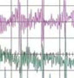
Electrical noise interference from motors and drives is affecting our sensor signals and HMI.
Too often, the sensor signals and even the HMI of our metal-cutting machines go haywire, largely because of electrical noise interference from many old, large, nearby motors and drives that we really can't replace. One solution suggested is to start using fiberoptic cable for signal transmission, but that's not cheap. Alternatively, there also are dozens of power filters, uninterruptible power supplies and other power conditioning devices out there, ranging in price from less than $100 to more than $1,000. We could use some information about both alternatives to help sort out the best course of action.
ANSWERS
Try These First
Following are a few basic design rules that might take care of the problems.
Separation between the low voltage control and high voltage power lines: If those lines need to cross, they should do so at 90° angles.
Use shielded cables and/or shielded cable trays. It is important to note that simply using what is typically sold as shielded sensor cable could actually increase the problem, especially when using cables with M12 connectors. Most such cables do not connect the shield to the coupling nut and, as a result, do not provide a clean path to ground.
Provide for solid machine ground interconnections. This is a must when using shielded cables or the shield will serve to equalize the potential between the different machine sections.
Use ferrite chokes.
Reduce the length of the sensor cables. In this case the sensors are connected to field-mounted I/O modules that communicate over a network with the PLC. For this, AS-Interface is especially suitable due to its simplicity and flexibility. Also, the nature of the design gives this network high inherent noise immunity and bulletproof error detection, combined with automatic data retransmission methods.
Helge Hornis, Ph. D., manager, intelligent systems,
Pepperl+Fuchs
Good Earth Ground
Make sure that all the equipment is grounded to a single point, also known as “star” point. This star point should go back to the power supply ground. This will help to reduce ground loop currents. In conjunction with this, use in-line toroid filters with the power supply lines to each piece of equipment. For sensors, use L-C feedthrough filters between the sensor and controllers or PLC. The filter frequency range should be DC to 50 MHz with attenuation of 30 dB or more. The filter ground must be connected to Earth ground.
Karmjit Sidhu, vice president, business development,
American Sensor Technologies
Electrical Isolation Is the Answer
The need for isolation can take on many forms based on the types of signals and environmental issues in a particular location. Types of isolation can include signal isolation, power isolation and data transmission isolation.
To reduce the effect of electrical noise on signals controlling machinery and other equipment, a combination of two technologies prove to be the most effective. These technologies are optical coupling and inductive coupling.
Generally, signals produced by sensors have low levels and are thus susceptible to capacitive and inductive interference, such as those generated by motors, drives and other processes. One method to protect against noise-related issues is with the use of signal isolators/conditioners that use optical and inductive technologies to isolate signals.
The best signal conditioning solutions use optical isolation between the input and output signals and magnetic isolation of the power supply from the input and output. This is commonly referred to as three-port isolation.
This type of solution can be implemented quickly and easily for between $100 and $150 per point.
An additional way isolation can be improved is effective wiring practices. Depending on length of sensor cabling run, voltage signals are easy to use but provide voltage drops when cable lengths exceed even a few feet and can be expensive if larger conductors are used.
Conversion to current signals could benefit because a shielded twisted pair of conductors can transmit a 4-20 mA signal over very long distances. Earth grounding the shield at one end will help provide protection against electrical noise.
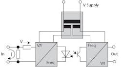
For example, the input signal is converted by means of pulse-width modulation into a frequency signal and demodulated again on the output side to form an analog value. An amplifier then generates a standardized analog signal. A galvanic isolated DC-to-DC converter feeds the input and output circuit with a potential-free supply voltage. It also determines the isolation level through its data, air and creepage distances. Galvanic isolation means the circuit is separated from the signal source in such a way that DC current cannot bridge the connection.
Often a larger power supply is used throughout a machine, electrical panel, process or any equipment. On this shared DC power bus, there are usually devices that produce electrical noise. The noise can interfere with other equipment on the power bus. This noise can be isolated by using a DC-to-DC converter, which often uses optical and magnetic isolation to limit the electrical noise passed along. This type of solution can usually be accomplished for around $250 per power bus.
As with signal isolation, powering isolation can be greatly improved with the use of efficient wiring practices. This is one of the most overlooked factors of induced noise.
Separating signal and power in a cable run is always a good idea. Grounding a cable only on one end without the use of a signal isolator is another often overlooked practice. Grounding a signal cable on two ends will very often lead to ground loops and signal inaccuracies and could even be a safety concern. We recommend using signal isolators that allow you to ground the equipment independently from the sensor.
The last major category of isolation centers on data communications. The most efficient method to accomplish this is through the use of fiberoptic cables. Fiberoptic cables are not as susceptible to electromagnetic interference as are copper networking cables such as Cat. 5 cables.
The use of fiberoptic cabling is definitely an option if you are communicating the sensor information via some bus system or communication medium. An example would be having the sensor providing the measurement of the physical property, providing the signal to a communication location and then transmitting the information via an Ethernet fiberoptic media to a controller or HMI. The downside of doing this is that this solution is usually very expensive. The same can be said with DeviceNet, Profibus and Modbus. There has to be some type of smart device, often using a proprietary protocol, to put the sensor information onto a data stream that can be transmitted via fiberoptic cable.
Alan Stewart, application engineering manager,
Weidmüller North America
Protect and Filter
Going to fiber optics is one solution, but unlikely to fully solve the problem. I am going to guess the noise issue is on the signal and power lines in this facility.
Faced with a budget, the best place to start is to reduce the amount of noise placed on the low-voltage signal wires. Are these wires shielded? If not, replace the cables with ones that have shielding. If so, is only one side of the shield grounded? Are these cables run near the power cables? The farther away you can put these from each other the better. This might not be possible in every case, so ensure the cables are not run parallel, but if they do cross, then have it at a 90° angle. In some cases you might have one or two sensors and cables that are problem cases. Check to see if an optical isolator is an option for these cables and install it inside the control cabinet.
The noise is also efficiently transmitted back from the motors and drives to the sub-panels. From there it is distributed to all the connected equipment. There are two items that I think also help reduce this noise: surge protection and noise filtering. Some products combine both, reducing the space needed and installation cost. At these sub-panels, install this protection and filtering. These products take the noise of the lines and put it on the ground.
The last thing you can do is ensure your grounding and bonding system is good. The noise is going to be dumped onto the grounding system by the sensor shielding, surge protection and the noise filtering. Verify you have a good mechanical connection on the ground wire. Check it as far back as you can in the electrical system.
Ed Doherty, product marketing manager—Trabtech,
Phoenix Contact
Sound Advice: Shield Connecting Systems
Shield connecting systems are a cost-effective noise abatement method as they intercept, redirect and dissipate the noise that affects both digital and analog signals. The systems typically feature a shield clamping saddle, carrier, carrier rail, insulated mounting foot and mounting accessories.
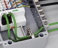
These systems provide close proximity of the clamping unit to the unshielded part of a cable, ensuring signal integrity. The spring material portion of the clamping saddle provides excellent electrical connectivity while compensating for any braiding deformation. Particularly sensitive connections can be shielded right at the inlet or prior to signal terminals, depending on installation. The system also functions as strain relief.
Fiberoptic cabling poses specific challenges beyond initial material costs. It is much more labor-intensive and requires special care. Fiberoptic cabling requires a specific bend radius, which if not performed with care, can ruin cables. Conversely, proper shielding takes advantage of copper conductive cabling’s greater durability, as well as lower material costs and more efficient installations. A well-integrated shield system should easily meet electromagnetic compatibility standards in a cost-effective manner.
Michelle Goeman, product manager—terminal blocks and electronic interface,
Wago
Check the HMI
Make sure the drives and motors, even though old, have separate isolated power grounds. The grounds for these should be pulled directly to building steel, not landed on a backplane of a control cabinet. If they are, they introduce mega noise into the ground.
All instruments should have continuously shielded communication, signal and power cables for maximum protection. Do not depend on your cabinet to shield your devices or cables. The HMI cutout is a giant hole in the shielding capability of a cabinet. And by the way, non-metal cabinets do not provide any shielding from noise. There are other ways noise can get in also, so do not terminate your shielded cable on a terminal block and then run a piece of unshielded cable to your instrument or PLC. Shield it all the way from device to device. Continue shields through the terminal blocks.
The shields should be grounded. There are two schools of thought on this nowadays. The way I learned it was to ground all shields at one end. If you ground it on both ends, you create a large antenna to catch noise. The second school is to run a ground conductor from one cabinet to the other to make sure they are all at the same potential. Then ground your shields at both ends. I have not bought in to this yet, but it is becoming the recommended standard.
Make sure the HMI communications cable is shielded. Although it’s not required by most, it’s still a good idea to make sure the HMI power cable is shielded. Make sure the power supply has a good ground and that the panel is grounded. Make sure the PLC has the same ground as the HMI, if possible.
Keep all communications and signal wires away from any power cables going to or leaving the drives or the motors. If they must cross, make sure they cross perpendicular. Never run them parallel.
Ground all sections of the machine. Do not depend on the cabinet for grounding. Use ground straps. Even put a ground strap from the door to the cabinet body. Finer stranded wire makes for better grounding, which is why grounding straps are made of lots of tiny wires, not larger gauges. The skin effect is what makes for good noise grounding.
Use the correct impedance and termination resistors for the communication cables.
Robert Thornton, product manager,
AutomationDirect
FEBRUARY’S PROBLEM
Many of the inputs on our machine automation systems require extensive signal processing for filtering, averaging, and other calculations. We know that PC-based control would be a good solution, but our customers require us to use a PLC. Unfortunately, the PLC brands specified don't include much in the way of signal processing capability at the I/O. This drives us to use a quite expensive model of the specified brand of PLC, even though our I/O counts are low and our other automation requirements are quite simple. However, our customers would accept a PLC with at least some I/O from a vendor of our choice, a vendor specializing in I/O with signal processing and other capabilities. Can we easily mix and match I/O from different vendors with one PLC processor, providing that PLC processor contains industry standard digital network interfaces? Are they any gotchas?
