Integrated axes crank up cold working
By Marc St. Pierre, Ingersoll CM Systems
Ingersoll CM Systems, Midland, Mich., is a leading developer of crankshaft manufacturing systems and machinery. The company produces special equipment used in crankshaft manufacturing, including its crankshaft deep fillet rolling machines. The machine induces compressive residual stress at and below the surface of the crankshaft being rolled or cold worked. The automotive, truck, and off-road industries have used this method for many years, and its proven to be a reliable and cost-effective method to improve the fatigue strength of crankshafts.
Multiple Axes, Multiple Forces
Depending on the crankshaft requirements, specifically if the crankshaft is for a four or six-cylinder engine, the rolling machine includes from nine to 13 arms of independent rolling axes per machine, says Gary Munger, Ingersolls controls engineering manager. Each arm applies a different force at a different point along the length of the crankshaft to condense and strengthen the crankshaft. In some cases, the rolling machine is used to restore a crankshaft thats found to have an unacceptable amount of distortion after rolling. In this case, a higher load force is applied selectively. One proportional hydraulic valve is assigned to each rolling axis of motion on the machine. The overall machine is controlled by the motion controller, which tightly integrates the multi-tasking PLC with the CNC, and is capable of controlling up to 64 axes of motion (See Figure 1 below).
The rolling machine includes nine to 13 arms of independent rolling axes, each arm applying a different force at a different point along the length of the crankshaft. The overall machine is controlled by the motion controller, which tightly integrates the multi-tasking PLC with the CNC and is capable of controlling up to 64 axes of motion.
Previously, Ingersolls rolling machines used separate control cards for each of the up to 13 axes of hydraulic motion, says Munger. This meant a larger processing area on the machine, expansive cabinet space for individual controllers, and excessive wiring for components and I/O. The previous version of the valve controller used an analog interface, which added a great deal of field wiring and panel space, along with the normal challenges of signal noise. But as crankshafts have become more compact, Ingersoll wanted its next generation of crankshaft rolling machines to be more compact.
Munger says Ingersolls primary control package requirements for the machine were that the system supply incremental, precise pressure variations for a resulting force up to 30 kN with a ±1% tolerance band. In addition, the hydraulic actuator had to execute programmed force changes in 0.1 sec.
Ingersoll CM Systems has a relationship with a number of automation suppliers and, in this case, called on the hydraulics and electric drives and controls groups of Bosch Rexroth to provide a control solution that would help them satisfy industry demands for greater crankshaft strength and precision as well as faster crankshaft production.
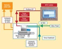
Ingersoll now uses Rexroths IAC-R axis controller proportional valves with integrated motion control on the hydraulic axes and combined them with a Rexroth IndraMotion MTX controller.
We actually use other controllers as well, but the IAC-R hydraulic valve remains a constant in our designs because were not aware of another device with the same functional capability for on-board axis control and a digital interface, says Munger.
Proportional valves with electronics directly on the valve have been widely used for some time. However, the control of the hydraulic drive axis has normally required a separate axis motion controller. The Rexroth valve provides a programmable, fieldbus-compatible, 32-bit digital motion controller for the hydraulic axisall packaged on a servo solenoid valve. The axis feedback devices, including position, pressure and force, plug directly into the valves onboard electronics. The result is a completely integrated assembly for electro-hydraulic motion control that significantly cuts panel space and wiring requirements. These advantages become available with the use of distributed digital intelligent devices such as the IAC-R hydraulic valve, fieldbus I/O, and electrical drives.
Faster, Smaller Achieved
The use of the IAC-R valve reduced field wiring by 25% and eliminated a 24x48-in. electrical panel used for analog I/O and wiring (See Figure 2 below), saving us approximately 10% in machine control costs, says Munger.
The use of the IAC-R valve reduced field wiring by 25% and eliminated this 24x48-in. electrical panel that housed analog I/O and wiring.
The solution includes PLC communication with the motion axes over a Profibus network. This, coupled with distributed intelligence in the valves, removes limitations in control performance commonly associated with continuous, closed-loop control concepts over a fieldbus.
Essentially, logic execution and synchronization are much faster, says Munger. Were able to achieve a PLC scan time of less than two milliseconds, which is more than 10 times faster than the other controls we used recently. It all adds up to greater precision, a critical factor in this industry.
We looked at other valves with pressure feedback and closed-loop control based on direct pressure, but the valves derive their measurements instead of actually measuring them, explains Munger. The IAC-R valve measures the force. In a system that measures hydraulic pressure only, there is potential for a failed actuator or other mechanical device to build pressure and satisfy the system without performing the work intended. With our feedback system design, force must be applied through the workpiece for the control to be satisfied. This ensures consistent, accurate force application and a good workpiece every cycle.
Munger also noted that all setup parameters for the digital controller are saved in Flash Memory on the valve and stored at the machine-level control. This allows quick configuration of series machines and minimum downtime in the field in the event of machine replacement. All parameters can be saved and uploaded or downloaded as needed, whereas before this was a manual adjustment. As a result, field changes can easily be made from one machine to another, taking less than half the commissioning time required in previous designs. On previous machine designs, a technician could spend four hours or more calibrating a machine. Now this task can be easily done by a machine operator in less than one hour.
A Complete Solution
The overall machine is controlled with the MTX CNC controller. The performance CNC card running the CNC motion and all machine logic is installed in an industrial computer located in the main electrical enclosure. A single cable connects the 15-in. display panel in the slim operator console, providing keyboard, machine key, USB, and mouse functionality. In addition, the software package used with the controller offers all the tools necessary to engineer, commission and operate the machine. The operator interface easily can adapt to fit the machine and operator needs using an integrated custom screen editor.
The MTX controller provides fast PLC program execution and expedient processing of NC-blocks and auxiliary functions for reduced controller-related time delays and improved machine productivity. Our scan time on a Siemens 840D is about 35 ms, whereas the same program on the MTX is about 2 ms, says Munger.
The MTX uses SERCOS with fiberoptic cable to control servo and spindle motion, and Profibus-DP to control distributed I/O and hydraulic axis control via the hydraulic valve controller. The valve has five modes of operation: open-loop flow control; closed-loop pressure or force control; position control; alternating control (closed-loop position and pressure); and onboard NC functionality. Feedback devices can be either analog, SSI, EnDAT, or 1 V p-p sine wave. Each valve counts and stores the power on time, operation time, and fault history as well as first, last, and next service dates for troubleshooting and preventative maintenance. A 64-character device description can be assigned to each valve and, like all parameters, can be read by the PLC or other control system via fieldbus.
The cast aluminum housing, containing the on-board valve electronics package, allowes IAC-R to be rated for IP65 sealing, EMC compatibility and sustained vibration of 25 Gs for 12 hours in all three dimensions.
Brian McMinn, sales engineer for Morrell, the Rexroth distributor supplying Ingersoll, noted that Morrell and Rexroth have committed to stocking IAC-R valves for Ingersoll because they typically build a rolling machine in less than 26 weeks, making delivery critical.
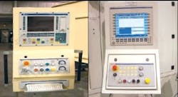
The move to IAC-R valves and the MTX controller also provides an aesthetic improvement, according to Munger, as the operator interface pendant has a smaller, slimmer look (See Figure 3 below).
FIGURE 3: BEFORE AND AFTERThe benefits for our customers are that they can check processes frequently, check forces daily or weekly, adjust and calibrate as needed via the operator interface, and send information directly to the valve, explains Munger. Before, they would measure with a voltmeter and potentiometer, which meant calibration would take more than twice as much time.
A Hot Idea for Cold Work
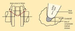
As the name implies, the crankshaft deep fillet rolling machine rolls or cold works the fillets or undercuts located at each end of a crankshafts bearing surfaces. Deep fillet rolling is the name given to the process of rolling under high loads. The term indicates the depth to which the material is strengthenedup to 0.125 in.
Rolling is one method of cold working in which a metal strip passes through a narrow gap between two rolls to produce additional dislocations within the metal structure. A dislocation is a defect in the metal lattice where atoms in a layer of the metal are missing. When two or more dislocations meet, they hinder each others movement, which increases the strength of the metal, making it stiffer, less malleable, and less ductile. In other words, it is more difficult to change its shape. To achieve this strength, the crankshaft is revolved a specific number of times within the deep fillet rolling machine at the required rolling force measured in Newtons.
| About the Author |
Marc St. Pierre is director of technology and Engineering at Ingersoll CM Systems, Midland, Mich.


