Mathieu Desmarais is project manager at Axium.
Welding is the process of heating, melting and joining materials such as metals and plastics to create a single part. It is performed in all major manufacturing industries including automotive, aviation, construction, oil and gas, and computers.
These joints might experience fatigue and exposure to loads, so it is critical that welds are done properly and to specification to prevent future failure.
The Axium Group, headquartered in Montréal, designs, builds and implements high-speed, automated assembly systems for manufacturing. These include solutions for welding and assembling components on plastic fuel tanks.
The company is composed of several entities: Axium, Lupar, Enico and SPG. Axium was founded in Montréal in 1998 by Robert Jodoin, an electrical engineer with a specialty in robotics, and mechanical engineer Sylvain-Paul Morency. Later, mechanical engineer Marc Ducharme joined them. Since the beginning, Axium grew at a constant rate through three main business units: process and integration, factory automation and material handling (picking, packing, palletizing and warehouse automation). As the company grew, Axium focused on robotic material handling and assembly lines and acquired other competences to become the Axium Group. It is now comprised of an electrical division (Lupar), a specialist in process and automation (Enico), and a vision entity specialized in 3D application for inspection in high-precision applications (SPG). Axium also started its activities in Europe and created Axium Europe in Croatia.
Naturally, Axium and SPG work together on all projects that include vision and robotics. Axium is a seasoned veteran in the field of assembly automation. Axium designs, builds, implements and supports innovative, high-speed automated assembly systems that deliver what we believe is unmatched reliability and repeatability for the manufacturing industry. Axium has a vast experience in assembly automation, having supplied non-robotic (hard automation) systems and robotic systems ranging from two to 15 robots and cycle times down to 48 seconds.
Also Read "Design Collaboration Tools With More"
Robotic Welding
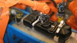
The company's robotic welding line performs all the operations required in the welding process using automatic or manual tank loading and unloading (Figure 1). Operations include hot plate welding, IR welding, internal welding, spin welding, cutting, manual operations and 3D vision inspection.
Axium's robotic welding line performs all the operations required in the welding process using automatic or manual tank loading and unloading. Operations include hot plate welding, IR welding, internal welding, spin welding, cutting, manual operations and 3D vision inspection.
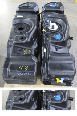
In the welding line, robots perform numerous tasks including 3D vision inspection of the welding of valves and components in place using the information from the vision systems.
(Before shot is top. After shot is bottom)
Safety requirements and environmental regulations make it critical to ensure the weld quality of every tank. SPG Vision and Robotics, a member of the Axium Group, manufactures digital 2D and 3D vision solutions for automated inspection, quality assurance and intelligent robot guidance.
Axium provides completely automated plastic fuel-tank welding and finishing lines. Just downstream of the blow-molding machine, the Axium system takes charge of the tank. First, the tank and flashes are individually weighed, and then a 1D or 2D bar code is laser etched on the tank while the flashes are removed. A robot takes each tank and properly inserts and retrieves it from the water cooling bath. The tank is placed on an exit conveyor and goes through an air-drying station to remove excess water. From there, tanks move to an automated storage and retrieval system (ASRS) and then to the welding line.
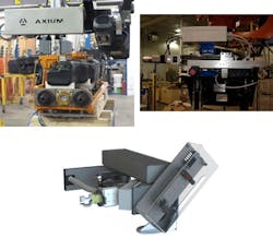
In the welding line, robots perform numerous tasks, including 3D vision inspection, cutting of holes for valves and components, and finally the welding of said valves and components (Figure 2) using the information from the vision system(s).
Finally, tanks move to a semi-automated line, where operators perform the final dress-out of a fuel tank before it leaves the factory. The line regroups all necessary features to complete a finished product that's ready to deliver to a customer.
Before the Welding Begins
"Prior to the welding steps, the system scans a region of interest (ROI), in this case, a weld pad—the surface feature on the tank where a component is welded or a hole is cut—that can vary in size and geometry—and dynamically adjusts the position and orientation of the welding tool," says Robert Battaglia, Axium supervisor—mechanical design. "This step has to be highly accurate and precise to ensure a minimum of off-quality scrapped tanks, since the components to be welded have to be centered and parallel to the weld pad, while minimizing the weld cycle time."
Because the system has to be fast enough to process in-line, and the point cloud density and accuracy need to be high enough to permit very robust and accurate feature extraction and location, a 3D scanner is the most appropriate option. SPG found, however, that commercially available 3D scanners were either too expensive or did not meet their requirements for accuracy and robustness.
"We needed a solution that works in an environment where the surrounding light cannot be controlled and recognizes that the laser power needs to stay in the eye-safe range (class 2M or less)," Christian Simon, SPG vision software development manager, explains. "To ensure the system is immune to various ambient light intensities, an appropriate bandpass filter must be used on the camera, and the laser light power must be maximized to decrease the camera exposure as much as possible.
We want to adjust the field of view of the scanner to exactly fit the needs of the application so all the available laser power could be used; however, off-the-shelf solutions do not have this optimal field of view, so we decided to build our own 3D scanner."
SPG developed the WeldSight-3D vision system to adapt to the fuel tanks' irregularities and variances that arise as part of the manufacturing process. WeldSight-3D uses a laser triangulation technique to compute a 3D point cloud of the ROI. The point cloud is then processed and analyzed to precisely locate features of interest (e.g., marker and hole) to compute alignment corrections and guide the robot with accurate coordinates and orientations.
Build Your Own Scanner
WeldSight-3D consists of a 3D scanner and software with an operator interface that communicates with a robot controller – independent of the robot's brand and model–to correct the position and orientation of the welding tool. "For this project, it connects through standard Ethernet, but we can support any standard communication protocol," Simon reports. "A typical 300cm² area is scanned within less than two seconds. This lets the tool adapt to surface irregularities. The positioning precision of the scanner is 0.06 mm, and the angular precision is 0.01 degrees. The system also computes quality features to reject tanks that have various production issues."
Also Read "E-CAD Gets It Together"
The 3D scanner consists of an AVT Manta G-033 B high-frame-rate 2D camera with an Edmund Optics TechSpec 650 nm CWL 25-nm bandpass interference filter, an MVnano 650-nm laser, a Festo EGSK-26 200-mm linear scanning axis combined with an Aerotech motion system that includes a NEMA 17 brushless servomotor, and an Aerotech Soloist MP digital controller.
The assembled 3D scanner system consists of a high-frame-rate 2D camera with a light interference filter, a 650-nm laser, a 200-mm linear scanning axis combined with an motion system that includes a NEMA 17 brushless servomotor and digital controller.
In essence, a 2D camera and a laser, in conjunction with motion--and overlapping images--and the software, create the depth measurement for the 3D point cloud model.
We chose those suppliers because they represent industry standards that provide quality products that are readily available at reasonable prices.
SPG uses the Matrox Imaging Library (MIL) development toolkit in all its 2D and 3D vision inspection systems. Depending on the application, MIL is used for image acquisition and segmentation, and object localization and analysis.
SPG uses Matrox Imaging's GigE vision driver to acquire images from the 2D camera, so acquisition is independent of a specific camera brand. "Because we already use the MIL, and we developed single driver software, we reuse it with different cameras," Simon explains. "This saves us from having to redevelop new drivers each time we use a new vendor."
The MIL's laser-line extraction function quickly and accurately detects the laser line in the 2D images. "This application's speed requirement allows the laser line extraction processing to take place directly on the PC," Simon adds. "And, because MIL is device-independent, this function can be used on other more powerful Matrox hardware when faster detection speed is required."
There are other vision library suppliers, but MIL offers us a comprehensive set of field-proven tools for development including feasibility testing, prototyping, application creation and deployment.
"MIL recently celebrated its 20th anniversary with more than 14,000 development seats and over 300,000 systems deployed across a wide variety of industries," touts Matrox product line manager Pierantonio Boriero.
Algorithmic Accuracy
SPG developed the mathematical algorithms to accurately calibrate the triangulation setup of camera, laser and axis. "This calibration allows the conversion of the detected laser line coordinates to a dense 3D point cloud," Simon explains. "The company also developed tools to find 3D mathematical planes in a point cloud. The found plane (e.g., weld pad surface) is then used to project the 3D point cloud to a 2D surface normal to that plane. Once the point cloud has been projected on the 2D surface, a re-sampling is performed to represent this projection in a 2D image."
MIL's powerful imaging techniques can be used to quickly and accurately find the features of interest (i.e., holes, circles and markers) in the projection image. The library's geometric model finder tool is configured to find the location of the main pad circle, as well as the hole in the middle of the pad. The tool's robustness ensures that it finds the pad circle even when the pad is not completely circular.
In addition, different MIL functions–including grayscale correlation pattern matching–accurately locate the stripe markers to completely align the tool relative to the pad. The features found in the projection image then are converted back to the point cloud coordinate and used to compute the alignment corrections and provide robot guidance.
The vision system also measures qualitative features to ensure good weld quality on every tank. "For example, the maximum deviation of points above and below the plane surface of the weld pad is computed, and tanks with large deviations are rejected," Battaglia explains. MIL's blob analysis tool computes the area of the foreign matter in the hole to ensure the cutting step has been completed properly. All values computed in the projection image are converted to real-world values to allow easy configuration of the rejected parameters by the user. The user interface graphically shows the position and orientation of the alignment and quality features. "If a weld pad fails inspection, the unload robot at the end of the weld line will put the tank on a reject conveyor so that it can be inspected by an operator." Battaglia concludes.
"Developing the calibration algorithm for high-accuracy measurement and developing the 3D point cloud projection algorithm into re-sampled images presented us with significant challenges," Simon explains. "Thankfully, Matrox Imaging Library makes it easy for us to find features in the projected images."
Simon adds that developing SPG's own algorithms for calibration and 3D data manipulation required a significant amount of investment, but we reuse these algorithms in a multitude of different projects. Having a good understanding and internal control on these critical algorithms is important for us.
Our calibration algorithm allows us to obtain maximum accuracy with a minimum investment in complex calibration target. Our 3D point cloud projection algorithm allows us to quickly transform a slow 3D feature search problem into a faster 2D imaging problem. In the re-sampled projection image, we can use the powerful MIL imaging library functions to locate features of interest quickly and accurately.
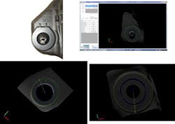
An example of a partial circular pad and features extracted in 3D point cloud generated from the scanning system and software.
A Look Ahead
We're now deploying several WeldSight-3D vision systems at Axium customer sites. All these clients are in the gas tank industry. Looking to the future, SPG plans to replace the standard PC with the Matrox 4Sight GPm industrial computer in most of its 2D and 3D systems, since the latter is much more compact and, therefore, easier to integrate in control panels.
"A fanless design with multiple ports for GigE Vision and USB3 Vision cameras ensures that the Matrox 4Sight GPm is at home on any factory floor," says Fabio Perelli, product manager at Matrox Imaging. "Plus it's powered by a mobile-class embedded third-generation Intel Core processor, so it has what it takes to cost-effectively handle multi-camera and even multi-line inspections."
SPG will continue to develop its 2D and 3D vision inspection systems using the Matrox development library, since it offers the robustness, accuracy and portability that we demand. "Since we implemented this technology many automotive manufacturers have been asking for it," Battaglia concludes.

Leaders relevant to this article:
