Encoders and resolvers—giving you a sense of where things are
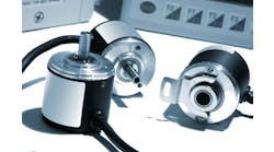
When it is required to measure the rotational angle or get speed feedback of a motor or shaft, the two most common methods used are rotary resolver or a rotary encoder.
Resolvers have been around for more than 50 years and are robust and reliable rotary position sensors. The resolver consists of a rotor and a stator, similar to an electric motor. Inside the resolver housing, the arrangement of the windings are such that one coil, effectively a rotating transformer, induces a voltage in the rotor. This voltage in turn induces voltages in two additional windings that are physically arranged 90° apart from each other. As the rotor turns, the induced voltages of the additional windings are 90° out of phase with each other in a sine/cosine relationship.
The raw outputs of the resolver are analog signals that are converted into digital values in modern devices. Since the windings are fixed in position, no matter the angle of rotation of the rotor, its position can be immediately determined by measuring the phase relationship between sine and cosine windings. Even if the rotor is turned during a power-off of the system, upon reapplication of power to the controls, the electronics can recalculate the rotor’s position.
Adding more pairs of secondary windings increases the accuracy of the resolver. For scientific resolvers, one rotation can be measured within minutes, or 1/60 of a degree, or even seconds, 1/3,600 of a degree. This accuracy is achieved using a device with 128 or more pole sets.
Resolvers are restricted in the speeds in which they can operate because of the inductive time lag, RL, and the input excitation frequency. Resolvers are very rugged, rather simple electromechanical devices that usually have their electronics detached from the resolver itself. However, the analog wiring leading from the resolver to the interface converter may be susceptible to electrical noise. Proper wire shielding techniques must be followed.
When used in a motion control system, the controller may have inputs to connect the raw output of the resolver. The output of the resolver may also be connected to a signal conditioner module that converts the angle of rotation into a digital binary value similar to encoder outputs. This signal may then be connected to most any digital control device.
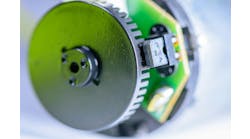
Rotary encoders typically use magnetic flux sensors—Hall-effect or magnetoresistive—or an optical light source such as an LED or laser. The magnetic style uses a magnetized gear-like rotor passing in front of the sensors. An optical rotary encoder uses a rotor made from etched glass, plastic or precision-machined metal to interrupt the light source from striking a photo detector producing a shutter effect.
The most basic encoders are incremental. A single-channel encoder has a single output that changes from an on to an off state multiple times as the rotor moves. The rotational angle is calculated by counting the pulses and dividing them by the total number of pulses in one complete rotation. If an inductive proximity sensor is used to count the teeth of a chain sprocket, this could be considered a single-channel incremental encoder.
A disadvantage of a single output encoder is that rotational direction cannot be determined with a single pulse. Also, if the rotor of a single channel encoder is positioned very close to the on/off switching point, vibration can possibly cause an error in counting. If those disadvantages are unacceptable in the design, a two-channel, or quadrature, encoder is used.
An incremental encoder typically has three output channels, A, B and Z. The A and B typically form the two-channel quadrature, square-wave outputs. Depending on which channel turns on first, the attached control device can determine if the encoder shaft is turning clockwise or counterclockwise. In one direction, Channel A turns on, Channel B turns on, Channel A turns off, Channel B turns off. In the other direction Channel B leads.
Some quadrature encoders have an additional channel, Z. The Z output turns on only once every revolution. This allows the control device to measure over multiple turns of the encoder.
When an incremental encoder is used and a power outage occurs, upon reapplying power to the system, the actual rotational position of the encoder is unknown. Some method of moving the encoder, motor or mechanical actuator to a known “home” position is required. For example, homing to a sensor and then resetting a position variable to some known value is common. The position is set to a position relative to the home switch.
Also read: Case Study: How this OEM controls in-line winders with pneumatics
A second type of encoder is an absolute encoder. The advantage of an absolute encoder over an incremental encoder is that, any time the system is powered on, the angle of rotation is determined immediately; it does not lose position information when power is lost. The encoder position signal is provided either by discrete parallel outputs or serial output.
From a parallel output standpoint, instead of having only two or three channels, an absolute encoder can have four, eight, 12 or another number of channels, depending on the pulses-per-revolution (ppr) resolution. As the encoder turns, a binary count output is produced. However, some absolute encoders do not produce the standard binary output pattern; instead, they produce a coding system called Gray code, or reflected binary code (RBC). Gray code differs from standard hexidecimal or octal by producing signals that only change the state of one signal line at each count interval allowing error detection if one of the signal outputs or connection wires is damaged.
The control system used to receive the absolute encoder position data must be able to decode the data. More electronics are needed in the encoder and more wires and inputs are needed to process the device’s output. The encoder output can also be encoded and output in serial form. Again, the device used to receive the signal must be specified to match the encoder output. Hardware requirements must be carefully met, as an open bidirectional/serial/synchronous (BiSS) interface protocol may not work with a synchronous serial interface (SSI) protocol. Carefully consider transmission speed and wire connections.
General industrial buses can also be used with encoders. But, while DeviceNet or Profibus may be available, the update rate and real-time synchronization of position data may drive the application to use a resolver or encoder with discrete signal outputs.
The resolution of incremental and absolute encoders is commonly available up to 8,000 ppr or so, but resolutions well over 250,000 ppr are available. Maximum rotational speed must be considered, but many encoders, often built with ball bearings, can rotate at very high speeds. Maximum rotational speeds of 10,000 rpm are common.
Encoders often have electronic components built within the housing to provide differential line driver, open collector, push-pull and other output types with normal output voltages of 5, 12 and 24 Vdc. The differential line driver is a good choice for output, and yet selection is dependent on the device the encoder is connected to. Regardless of the signal level, the electronics will be subject to any shock, vibration and temperature variance the encoder is exposed to.
If the encoder resolution and speed is very low, the encoder can be connected to the standard digital inputs of a control device. Some control devices have special inputs that can be configured to act as high-speed encoder connections or offer high-speed counter input modules.
Both resolver and encoder devices are available with a wide variety of environment tolerances, many different physical mounting options and variations in the sensing technology. Selecting what to use is going to be heavily influenced by the manner in which it will be used.

Leaders relevant to this article:


