PLC+HMI enables critical stress testing


Bryan DeCelles is software engineer at AeroSpec. Contact him at [email protected].

Zach Marinella is mechanical engineer at AeroSpec. Contact him at [email protected].
Medical devices used in hospitals and clinics around the world must undergo a series of rigorous tests to evaluate their reliability before coming into contact with patients. With the high stakes involving patient health, sometimes life-or-death situations, there is no room for mistakes or faulty devices. Each tool in a medical staff’s arsenal must function flawlessly every time.
With these demanding requirements in mind, AeroSpec, a custom equipment manufacturer in Chandler, Arizona, developed its medical device test system (Figure 1).
This system is designed to perform endurance tests on new medical devices to ensure high-quality performance when met with load and stress from actual use. The system helps medical device manufacturers run extensive tests to ascertain optimal designs, verify reliability and ensure robust products.
AeroSpec started as a machine shop more than 30 years ago and quickly evolved into a full-service custom equipment supplier for a variety of industries including automotive, semiconductor, medical and others. AeroSpec's OEM equipment provides customers with low-cost and efficient methods to verify their medical devices have been tested and are ready for use in the field, whether these devices will be used in a walk-in clinic or an operating room.
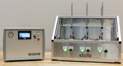
Figure 1: The heart of this medical device test system is the PLC+HMI, which performs control and monitoring of the system and provides operator interface.
Initial design
The AeroSpec medical device test system is a cost-effective, pre-designed solution based around the IDEC FT1A PLC+HMI controller and operator interface unit. Versatility is a strength of the system, as it can be adapted to run tests on a wide variety of medical devices.
Using the PC-based programming software supplied with the PLC+HMI unit, AeroSpec developed a powerful program to control the unit, and a key feature of this design is the test system’s ability to operate lean assembly and testing fixtures.
AeroSpec began work on the test system based upon client-requested specifications. Their client needed a system to run endurance tests on the new product, a cosmetic surgery device used for cellulite reduction, with the ability to simulate the load on the product and measure the stress endured by the device.
Also read: 4 must-read articles exploring the current state of the PLC
Initially, the request was for a test system that would measure current draw through the power cable of the tested device, but the client changed direction on the product to move to a wireless model, making the original request obsolete.
To comply with client requirements, AeroSpec opted to add an rpm sensor to measure and chart the change in velocity of the motor in the device. The rpm sensor would also provide the client’s engineers with critical data verifying the device could withstand real-world usage. This system was designed to allow AeroSpec’s client to run tests with wired devices, determine an optimal running current and copy that model to the wireless versions of the devices to continue testing.
Functionality and features

Figure 2: Medical devices are installed in three test fixtures and subject to conditions simulating actual operation in the field.
The test system is designed to execute endurance tests that assist medical-device manufacturers in the development of new products. The test system accomplishes this by simulating actual operating scenarios and by measuring the stress on the devices installed in the text fixtures to gauge how they perform (Figure 2).
The test system has three channels running in parallel with each other. When testing the endurance of medical devices, the test system controls and monitors three pneumatic actuators, three high-speed sensors that gauge rpm on the motor modules and three electromagnetic brakes. The brakes are used to simulate a load on the device, and the pneumatic actuators are used to activate and deactivate the devices.
The test system provides two main fault-condition alerts. The first condition—failed to activate part—occurs when the test system attempts to switch a device on and observes that the rpm reading from the motor module is not increasing. When this occurs, the test system tries to reactivate the device. If it fails to activate a device three times in a row, the test system provides a fault message. The second fault condition—failed to deactivate part— occurs when the test system attempts to turn off a device and doesn’t observe the rpm dropping to an acceptable level.
For both fault conditions, the test system flashes a red light for the station that failed to activate or deactivate a device. In a situation where one of the stations fails, or if the user attempts to initiate a cycle with the part incorrectly secured, the HMI screen will also display an alarm.
Hundreds of alarms can be recorded in the PLC+HMI unit alarm log file. Each alarm is accompanied by a brief description to inform the operator of the nature of the fault, and by a time and date stamp. The operator can select a particular alarm and click on the help button, and the PLC+HMI unit will open an alarm help screen where more information and helpful tips will be provided. This makes the process of troubleshooting different faults intuitive and enables the user to take corrective action promptly.
To reset the test system, the operator simply pulls the device out of the test fixture and then reinsert it, or press the reset button. In both cases, this will reinitiate the test cycle.
Combo PLC+HMI
AeroSpec’s medical device test system is responsible for critical product testing, and it’s powered by IDEC’s FT1A Touch, a combined PLC+HMI in a single housing. AeroSpec felt the IDEC unit was the best option for its test system as it allowed AeroSpec to attain design goals with a compact form factor unit at a competitive cost.
Another reason for selecting the unit is that the PLC part of the FT1A Touch provides the intelligence and logic needed to control the test processes as it’s a 32-bit-based controller with built-in arithmetic, trigonometric, exponential and logarithmic functions to handle the required high-level mathematical calculations.
The PLC has Modbus RTU and TCP ports, with TCP used in this application to communicate between the two PLCs: the master PLC and the slave PLC, which was used as a distributed I/O block. It also has a USB port to allow AeroSpec’s customer to download programs to the unit for control and monitoring of the test system. The PLC has sufficient memory to allow the program to expand and to cover the depth of the logic needed for the test procedures.
The HMI part of the FT1A Touch has all the features needed for executing tests and for observing results visually and efficiently. The HMI provides the test system with the graphical capabilities required to set up the tests and displays the current cycle and test number for each station (Figure 3).
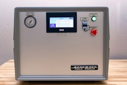
Figure 3: The HMI screen is configured to show all of the test parameters of interest and to guide the operator through the test procedures.
The HMI sets the parameters used to run the tests, including minimum and maximum test cycle times, number of tests performed and simulated load amounts. There is a screen for each station that displays an active trend of the rpm and the current test cycle. Located to the right of the screen are options to navigate to the parameters for each station including a histogram of the rpm, test cycles, use-life cycles and torque set points.
The test system requires very little training for an operator to use it effectively. An operator simply places the device in a test fixture, and, with no further input from the operator, the machine automatically cycles and tests the device.
When testing is complete, a green light for that station begins blinking, and the operator removes the tested product. The entire process is fast and efficient, and an operator can be trained in less than five minutes to perform these functions.
Due to the nature of the testing, the cycle time can be high, but it is also completely variable. Since the machine possesses three stations, the operator can test three devices simultaneously, tripling the number of devices that can be tested.
Test system specs
The entire test system is compact enough for desktop operation. Despite its compact size, the system houses impressive capabilities. It continuously logs each station's test data, such as rpm, electromagnetic brake force and station count, at a sample rate of about 500 ms. Data is logged for the duration of the test cycle, which is typically 10 minutes with 25 tests per cycle.
The test system is offered at prices starting at $5,000 and can be made to order in five to six weeks. In addition to the above-mentioned control and monitoring features, the test system includes the electromechanical components required to secure and test products. The test system can be expanded to include features such as thermal and vibration readings.
The test system includes:
- a PLC with up to 24 discrete inputs, 12 discrete outputs, six analog inputs, four analog outputs and four high speed counters
- an HMI touchscreen
- test fixtures
- three variable-force electromagnetic brakes capable of supplying forces from 0.01 Nmm to 20 Nmm with 0.01 Nmm resolution
- pneumatic and solenoid valves
- other components as required for testing a wide variety of medical devices.
This initial implementation of the test system is only the beginning. Several of AeroSpec’s customers are currently working with them to adapt the system to meet specific medical-device test requirements. This flexibility of the test system, powered by the PLC+HMI unit, makes these types of adaptations feasible and allows for new implementations to meet customer demands.
