PLC vs. Arduino for industrial control

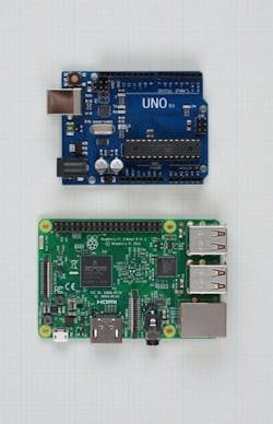
Figure 1: The Arduino and Raspberry Pi platforms have many capabilities but also lack many practical features to support easy implementation in industrial applications.
(Source: Peter Welander and Doug Reneker)
The “maker” world of basement robot builders continues to grow, with companies developing hardware and software to support all sorts of interesting applications. A number of micro-controllers have emerged to perform a wide variety of functions at very low upfront hardware and software costs.A large number of boards, including micro-controllers, field programmable gate arrays (FPGAs) and single-board computers, have emerged. Among these, Arduino and Raspberry Pi are two leading names (Figure 1). Both are open-source devices, with components available from a variety of suppliers, and both require a high level of programming skills and some imagination before they can be used for real-time industrial control applications.
Some industrial users might envision these platforms as a substitute for an entry-level PLC. After all, if an Arduino can control a robot for a STEM competition entry, why can’t it control an industrial robot, or a simple machine? If it’s possible to buy an Arduino for as little as $20, why spend hundreds on a PLC? An Arduino can do lots of things, but as I discovered, making it work in even a simple industrial application is easier said than done.
Real-time industrial control with an Arduino
The Raspberry Pi is effectively a miniaturized Linux-based single-board PC, whereas an Arduino is more like a PLC. While either platform looked suitable, I settled on the Arduino for our project: closed-loop control of flow generated by a pump. A sensor measures flow and sends data to the Arduino, which adjusts a control valve actuator to maintain the setpoint. This is one of the most basic industrial analog automation functions and often uses a PID loop as the control algorithm.
The Arduino uses PI control capability—it doesn’t need derivative for this type of loop—to read the signal from the flowmeter and adjust the valve to reach and maintain the setpoint. The concept is simple enough, but, when working with real-world industrial equipment, it gets more complicated.
The Arduino is a bare-bones device, as befits its price, but it does have extensive capabilities if the right program can be written to match the application. It’s a totally blank slate for a programmer, with no native capabilities or function blocks ready to upload, so I had to create the PI algorithm from scratch.
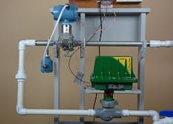
Figure 2: This flowmeter and valve represent typical industrial equipment often used to control flow.
(Source: Peter Welander and Doug Reneker)
It has both discrete and analog I/O; however, the selections are limited. Analog inputs are 0-5 V, and the analog outputs are pulse-width modulation (PWM). This is suitable for regulating the speed of a motor or for modulating a temperature control loop, but not so good for many other applications. Most industrial analog instruments and actuators are designed for 4-20 mA current loops, so this standard was used in the demonstration project, requiring quite a bit of design and engineering effort.
Dealing with current loops
The demonstration equipment uses standard off-the-shelf industrial components: A Rosemount 3051SFP Integral Orifice flowmeter and Fisher Easy-Drive control valve, both provided by Emerson Automation Solutions (Figure 2). These were not selected for any specific capabilities or characteristics beyond their physical size. They are both very common types of devices, making them very appropriate for this demonstration.

Figure 3: The signal converter board is in the middle of the Arduino shield stack. It converts the two current loop inputs and changes the PWM output to a current loop to control the valve.
(Source: Peter Welander and Doug Reneker)
The first step is converting the 4-20 mA signal coming from the flowmeter to 0-5 V, or better, 1-5 V to retain the live zero. This is not an uncommon situation, and converters are available from multiple sources. However, in keeping with the DIY character of the experiment and to keep costs down, I created one from scratch (Figure 3). It was built on an Arduino prototype shield to mount on top of the main board. A simple 250-Ohm resistor converts the 4-20 mA signal to 1-5 V.

Figure 4: While pulse-width modulation is good for controlling a motor or heating element, it must be converted to a voltage or current loop to drive most other devices.
(Source: Peter Welander and Doug Reneker)
The more challenging task was converting PWM to 4-20 mA. The lack of commercial solutions suggests this isn’t a common conversion, so I had to build this converter from scratch (Figure 4). I decided to electrically isolate the 4-20 mA current loop output using a two-channel optoisolator to allow more flexibility in connecting with other current loop devices. This leaves the problem of powering the circuit, as it is isolated from the power supplies. This was solved by powering the circuit from the current loop itself, using a voltage-reference integrated circuit.
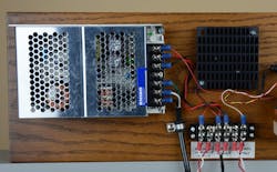
Figure 5: The flowmeter, control valve and most PLCs operate at 24 Vdc from the power supply (left). The Arduino operates at 12 Vdc, so an extra regulator (right) under the heat sink is necessary to operate it off the main power supply.
(Source: Peter Welander and Doug Reneker)
Arduino PWM outputs run at 500 Hz. A low-pass filter removes the 500 Hz signal and its harmonics, resulting in a dc signal proportional to the PWM duty cycle. A second-order Sallen-Key active filter was designed with a cutoff frequency of 7 Hz to provide sufficient attenuation of the 500 Hz component.
An operational amplifier (op-amp) is used to convert the low-pass filter output to current. Keep in mind that all the power supply currents—for the op-amps, voltage reference and optoisolator outputs—need to be less than 4 mA, as they must flow through the current loop. The resulting isolated output requires a maximum of 10 V from the 4-20 mA current loop for power, so it works quite well in a 24 V system. There was sufficient room to fit all the signal converting circuits on the same shield.
Basic infrastructure support
An Arduino has no power supply, nor does it have any type of human-machine interface (HMI), but it can use a small graphics display shield added to the stack, with a screen size of about 1.75 by 2.25 inches. Custom programming is required to provide useful information, unlike a PLC, which will typically have multiple HMI options requiring only simple screen configuration. Wire mounting is also rudimentary, so connecting the external devices takes some doing. Mounting the Arduino boards requires creativity since there is no enclosure, nor any handy options such as a DIN-rail mount.
For the demonstration project, I used a standard 24 Vdc power supply suitable for powering the flowmeter and control valve, but the voltage had to be stepped down with a simple linear regulator to 12 Vdc to power the Arduino (Figure 5).

Figure 6: Adding potentiometers to three of the remaining analog inputs allows the setpoint and the P and I gains to be adjusted, but there is no scale or indication.
(Source: Peter Welander and Doug Reneker)
Writing code to implement the PI algorithm on the Arduino had to be done from scratch but was relatively simple. The current loop input is read, the difference between the setpoint and the input evaluated, the integral and proportional corrections are calculated, and the result is sent to the PWM current loop output.
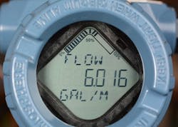
Figure 7: The transmitter on the flowmeter provides a local display that scrolls through a series of process variables in conventional engineering units. Using this, it’s possible to verify the performance of the loop.
(Source: Peter Welander and Doug Reneker)
To view operation, I wrote a program to use the small display to indicate both the process variable—read via the current loop input—and the control output as a function of time. This provides a direct view of the performance of the control system.The Arduino provides several analog inputs, so three more analog inputs were connected to potentiometers to adjust the operating factors (Figure 6). One controls the setpoint of the controller, allowing the water flow to be controlled at the turn of a knob. The two others provide the proportional and integral gains for the control loop and are manipulated to balance stability and response time. None of them have any scale or engineering units to indicate the setting.
Ready to run
The flowmeter has a default local display (Figure 7) showing the flow rate in gallons/minute (GPM) and differential pressure (dP) in inches of water to provide external indication of loop functionality. The PI algorithm performed as expected, and the loop can be tuned by manipulating the potentiometers to adjust the two control factors. Flow control exhibited the normal characteristics, good and bad, of PI loops.
There is a flow bypass valve, which can be used to cause changes to the process, forcing the loop to adjust the valve to maintain the setpoint. I created a program so the display can show a working representation of the loop (Figure 8); however, with the display’s size, it requires some effort to read.
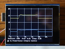
Figure 8: The display screen is the top layer of the Arduino board stack. While small, it can give a picture of the loop performance; however, all the functions, such as drawing the basic grid, have to be programmed from scratch.
(Source: Peter Welander and Doug Reneker)
The PWM-to-current-loop converter is the main bandwidth limitation. The necessity to use a low cutoff frequency to adequately filter the PWM limits how fast the Arduino can respond to a change in conditions. The 100 ms (10 Hz) sampling interval works well, once the proportional and integral gains are adjusted. If the bypass valve is open, it robs roughly half of the input flow from the system, but the Arduino adjusts the control valve to achieve the desired flow within a few seconds. With steady water flow, the system is stable, without any indication the control valve is making adjustments.
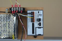
Figure 9: The AutomationDirect BRX PLC is well suited for this flow loop control application with built-in, industry-standard analog and discrete I/O and free Do-more Designer software for configuration and programming.
(Source: AutomationDirect)
Naturally, the Arduino has no concept of the engineering units it is dealing with, but then neither does a PLC. It is simply dealing with the current values, which is really all it has to do. Operators may want to see gallons or percent open, but it is not necessary for the controller.
Most industrial-grade equipment, like a PLC, is designed for use in potentially hostile environments where operation is critical and must be continuous. It can’t break down and quit simply because the plant gets a little too hot or cold. Most Arduinos are not built with this in mind. More industrial-grade units are emerging as are rated enclosures, but this consideration should be part of any analysis.
Real-time industrial control with a PLC
The second phase of the demonstration project used a basic low-end PLC, in this case a BRX (BX-DM1E-10ED23-D) from AutomationDirect. I came to this project with no prior experience with PLC programming or knowledge of ladder logic, making the comparison with Arduino objective, albeit more challenging than it would have been for an experienced PLC programmer.
The PLC has one analog output and one analog input, both configurable for 4-20 mA current loop operation, along with several discrete inputs and outputs. Programming access to the PLC is from an external Windows PC via Ethernet. The first step was downloading and installing the Do-more Designer software on a PC, a free download from www.automationdirect.com.
Once the software was installed, the PLC was connected to the PC with an Ethernet cable and powered up with 24 Vdc (Figure 9). A quick “ipconfig” command on the laptop revealed the Ethernet address of the laptop. A different IP address on the same subnet was programmed into the PLC via the Do-more Designer software.
The next step was learning a bit of ladder logic coding. Chapter 10 of the BRX PLC Hardware User Manual includes a step-by-step example of programming a simple timer using ladder logic. Working through this exercise provided a nice introduction to the software and to the basic programming structure of the PLC.
The analog input and output were configured for 4-20 mA current loop via the software. This was much easier than designing and building the current loop interfaces for the Arduino. After writing a couple rungs of ladder logic, a dc milliammeter verified the function of the output.
The PLC offers a sophisticated PID instruction, allowing the various loop parameters to be set for manual or automatic control of the loop. A very simple control loop was created by connecting the analog output back to the analog input, again using the milliammeter. Associating the PID instruction with the scaled analog input and output allowed the PLC to learn the PID function without handling several gallons of water. Active PI control was verified by “robbing” a bit of the output current with a resistor and watching the BRX PLC compensate.
Armed with this capability, it was time to integrate the PLC with our flow control loop. Connecting to the flow sensor was straightforward, with the 24-Vdc supply providing excitation for the flow sensor current loop. The control valve was even easier because the PLC current loop output provided the necessary excitation.
Firing up the system, it was a simple matter of using the Do-more Designer software to adjust the proportional and integral coefficients of the PID function to achieve stable flow through our system. Adjusting the flow was straightforward, with the setpoint adjusted via the Do-more Designer software.
The PID features of the Do-more Designer software provide self-scaling plots of both the process variable and the control variables, allowing clear, real-time monitoring of system performance.
Beyond the basic, core level of operation, the PLC offers a wide variety of the common support functions often needed in an industrial application such as limit detection, reporting and data recording. Compared to our Arduino demo, where each function must be written from scratch, this PLC allows the system designer to focus on the application and how it fits into a larger production system, instead of the details of controller hardware and software.
Make or buy?
So, which is better, the Arduino or the PLC? If only bare hardware cost for the controller and I/O are considered, the Arduino wins. But when all the ancillary components necessary to make the Arduino useful in this relatively simple application are added, the hardware cost gap will narrow or disappear. The time necessary to assemble and program the Arduino is also considerable. When this time is calculated at anything near normal engineering man-hour rates, the PLC is the clear winner in terms of overall cost.
Regarding performance, the Arduino and the PLC both did the job.
Although our project only looked at controlling a simple flow loop, most industrial applications will require a variety of other discrete and analog control functions. With a PLC, many of these are built in, but none are with an Arduino.
Someone experienced in C language programming might find the Arduino a quick study, but even the most basic industrial functions will have to be written from scratch. Someone who has never programmed either type of controller will have some work to do with either platform.
However, the number of online and other tutorials available for PLCs certainly weigh in their favor as they are aimed specifically at industrial users, with many function libraries available for downloading to perform common operations. For example, the PLC has loop-tuning software available, which would be very complex to write for the Arduino.
Equipment durability certainly weighs in favor of the PLC until more industrialized Arduino and Raspberry PI devices emerge. At the same time, most PLCs are part of product families, offering scalability and breadth of native capabilities, making it much easier to expand. PLCs with add-on I/O modules, HMIs and other ancillary equipment designed for mounting inside control cabinets will be far easier to work with and more time-efficient than Arduino or Raspberry PI platforms.
For someone learning the basics of code writing and concepts of control, the Arduino and its ilk provide interesting teaching tools. Having to write control algorithms from scratch causes a user to consider the intricacies of how automation is performed. The availability of devices with this level of sophistication at such low costs is quite remarkable and is a boon to those with more time than money.
But for an actual industrial application where production and revenue are at stake, a PLC with equivalent or better capabilities can be had for a few hundred dollars, and it will come with extensive online training videos and other information, and with function block libraries designed specifically for industrial applications.
About the author
Doug Reneker is a circuit designer, recently retired as a senior manager at Arris, a provider of broadband communications equipment for Internet providers and consumers. Contact him at [email protected].
About the Author

Doug Reneker
circuit designer
Doug Reneker is a retired electrical engineer and circuit designer who worked for Bell Labs, Recon/Optical and Arris. He has a BS and MS in electrical engineering from Iowa State University. Contact him at [email protected].
