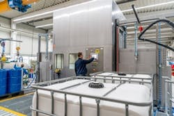
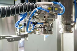
Figure 1: This turnkey filling line from Feige Filling fills drums, IBCs and small containers with potentially hazardous liquids and pasty products.
(Source: Feige Filling)
Filling above-level, sub-level or below-bunghole: This is what you hear when experts talk about drum-filling technology. Feige Filling, founded in Hamburg in 1972 and headquartered in Bad Oldesloe, Germany, is an international leader of gravimetric filling machines for liquid and pasty products with calibrated accuracy (Figure 1). In addition to automation and filling technology, the manufacturer develops explosion-proof (Ex) solutions for ATEX Category 1 because its filling machines typically operate in hazardous areas. To meet these requirements, Feige Filling relies on the universal Wago I/O System 750 at the I/O level.
They may be green, gray, red, blue or black, but they always contain 200 liters. Internationally standardized steel drums are widely used to fill potentially hazardous liquids, such as oils and chemicals, into robust packaging. To fill these drums, Feige Filling has developed a turnkey filling line that includes both handling and material flow processes. “Our customers want to fill and ship their products," says Martina Thomsen, marketing manager at Feige Filling. "They do not want to worry about how the drums arrive under the fill valve or end up on the shipping pallet. Drums are just one of many packaging types that the Feige Filling systems can accommodate. The spectrum ranges from 1 m³ intermediate bulk containers (IBCs) and drums to small containers, such as paint buckets from the hardware store.”
ALSO READ: Consider machine integration in the design phase
Safe filling in hazardous areas
Given the variety of packaging, it’s no surprise that the contents are incredibly diverse as well. Of course, these fluids all have properties—highly viscous, foaming, combustible or explosive—that can make the filling process extremely demanding.
Because of that, the filling valves are equipped with several safety functions. The valves are opened and closed using compressed air and fail safe close under spring force. The valve must also relieve pressure before disconnecting from the filled container. The fluids are also monitored for leakage during the cycle, and a level check is included to minimize dead space.
Additionally, Feige Filling systems must meet particular challenges, including ATEX directive requirements for the construction and operation of machines and systems used in hazardous areas. About half the filling systems that leave the company are approved for Zone 1 hazardous areas because explosion protection is part of its daily business. When configuring a system, both inputs and outputs are placed as close as possible to the process, where the signals are created and where they are transmitted. A goal is avoiding unnecessary wiring.
Figure 2: Feige Filling standardized on Wago-I/O-System 750, some designed for explosion-proof applications, to install the I/O close to the process, saving space, reducing wiring and making the system safer.
(Source: Feige Filling)
For filling process automation, Feige Filling relies on Wago's intrinsically safe modules from the remote Wago-I/O-System 750 (Figure 2). The modules can be installed close to the filling process for connecting sensors and light barriers on the input side, as well as solenoid and pneumatic valves on the output side. This saves both installation space and time by bringing the control system close to the process. Compared to star topology wiring, the control cabinet’s position within a production line is less important. This reduces engineering costs and simplifies the design of modular systems.
Another advantage of placing the I/O close to the process is that it helps to reduce energy stored by the system. This is energy that must be limited by the intrinsically safe modules. Cables are potential energy storage units, which is why it is always important to keep the length of cable runs to a minimum in hazardous applications. Distributed systems are better because shorter cable runs are shorter by design and simply store less energy.
Volume and weight
Figure 3: Filling system from Feige Filling located within an explosion-proof cabin.
(Source: Feige Filling)
Much of the technology in automatic pallet fillers is centered around the filling valve and weigh scale. The filling operation has been well developed over the years and starts with a coarse fill cycle followed by a fine fill (Figure 3). To meet the fill tolerances, it is necessary to restrict the volume flow near the end of the fill process. Both flow meters, to measure volume, and load cells, to verify minimum weight, are integrated into the system. This modular assembly system provides gravimetric filling of containers ranging in size from 0.5 kg to 3000 kg.
A touch panel provides alphanumeric entry of weight and volume requirements. More than 255 products, with expansion, can be configured and selected via the touch panel. The menu-driven display prompts the operator to configure the system. This includes product recipes, storage of operating data and setup to print to a label printer.
The weight scale records the operation data, logs the product weight results production data and provides statistical data for analysis. This data is available to networked devices or a USB flash drive.
One system, two application areas
The control system of a drum-filling machine is installed in a gas-tight enclosure that is purged to prevent explosive gas penetration. A touch-sensitive panel is integrated into the cabinet door, allowing the system to be operated and monitored locally. All of the system's sensors and actuators converge within the control enclosure both from the hazardous area, inside the hermetically sealed filling cabin where the fill valve and roller conveyor on scale reside, as well as from the non-ATEX system areas such as in-feed and out-feed.
Feige Filling relies on the Wago-I/O-System 750's intrinsically safe modules to connect every field device located in the Ex area of the filling system. The system is powered by a supply module that also monitors the power supply to the downstream intrinsic safety (Ex i) segment. Furthermore, this module separates the intrinsically safe from the non-intrinsically safe section. Feige Filling also relies on standard Wago-I/O-System components for the machine areas that do not require special explosion protection.
High availability through standardization
From a design perspective, only one I/O solution is used for system automation. “It is extremely important that our system designs are very similar to each other,” says Axel Frank, head of automation technology at Feige Filling. “Maximizing our system equipment standardization helps us minimize the probability of failure for individual components. Because the remote Wago-I/O-System 750 readily covers both hazardous and non-hazardous areas in one system, we can always equip the system automation with functional technology without leaving the stability of a standardized system.
Another advantage of working with Wago is its willingness to innovate. Wago kept advancing the Wago-I/O-System 750 to provide us with new items and didn't give up when additional requirements were needed. Wago's blue, intrinsically safe modules for Ex protection were not there when our partnership began.”

Leaders relevant to this article:


