Like most industrial automation components, variable speed drive design is trending smaller, yet more powerful and with more open communication. Motor and drive design has also influenced amplifier and inverter design to connect with more open protocols and network platforms. Four manufacturers—Schneider Electric, Weidmüller, Lenze and NK Technologies—discuss customized drive platforms and multi-axis systems, new communication technology for inverters and ground fault detection for variable speed drives.
Platform to drive
The desire for customized systems continues to push industrial automation development. To meet the tailored needs of more customers, Schneider Electric introduced the Altivar Machine ATV320 variable frequency drive in late 2016. “The impetus for it really was the need for a reliable, versatile drive platform for machine builders. The idea was to provide a standardized platform that you can build into any sort of industrial machine and get performance benefits using it,” says Richard Jennens, senior offer manager at Schneider Electric.
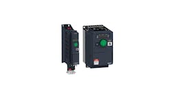
The range of adaptable concept packages for the drive were designed around that versatility, Jennens says. The one drive platform comes in three form factors. The compact version is a standard brick-like configuration and is ideal for shallow-depth panels with one or two drives. The bookcase version is designed for very narrow applications with minimal space above and below, and no horizontal space required between drives.
“You can minimize that panel space on the equipment, where you have a high-density requirement,” Jennens says. The third form—distributed enclosed—can be installed on machines in the production area. With an IP65, IP66 and UL Type 4X ratings, the drive works in dirty, dusty, humid or wet environments. “The drive is perfectly safe in there without requiring an enclosure, and that gives you the advantage of having the motor controls on the machine in the production area without having to spend extra on high-rate production enclosures,” Jennens says.
Energy efficiency and embedded safety are two trends pushing the variable-frequency-drive market, Jennens says. To optimize the performance of each drive, based on the application torque load, the Altivar platform offers six different motor control modes (Figure 1). It works with synchronous and asynchronous motors. In a variable-torque application, the standard and engine saving modes are designed to maximize the energy savings. “It’s tweaking around with the voltage and currents that go into the motor to maximize the performance benefits in those applications,” Jennens says. Custom modes can also accommodate torque applications that change speed in nonstandard way. “You can actually program in the custom curve into the drive, so it can optimize around that,” Jennens says.
Standard machine-safety functions have increased in the past few decades. “In today’s world, we’re a lot more safety-conscious,” Jennens says. “You see a lot of these standard safety functions being built into equipment, so things like an emergency-stop button, which will cause the machine to shut down.” In the past, to implement additional safety functions, the application would need additional hardware. Now, drives have safety functions built into the system. The Altivar ATV320 includes five machine safety functions—safe torque off, guard door locking, safe stop, safe limited speed and safe maximum speed. “You can implement those without requiring the extra contacts and relays, which otherwise would be extra hardware, extra wiring and extra space in the panel,” Jennens says.
Users also have the ability to put programmable logic into the drive. “So, for simple to medium complexity applications, you can use the drive as your PLC for a small application controller,” Jennens says. Again, this means less hardware, wiring, space and components. “Whether you’re using it for a standard application or one of the more advanced ones, you’re still using a standard component, so as an equipment supplier it simplifies your purchasing logistics and support chains,” he says.
The drive has built-in Modbus communications, but users can also insert a communication card to connect to any communication network that is being used in the plant or on the machine. “You can integrate it to your machine control system or to your plant control system for monitoring and troubleshooting, and that’s independent of the hardware platform you’re using for your control platform, so some manufacturers prefer using a particular communications platform, and you can slot in the card to connect to it,” Jennens says.
Connectivity, in general, is a big trend in the variable-speed-drive market, Jennens says. “It’s the ability to connect your process technologies with your information technologies,” he says. This has helped to enable growth in providing maintenance and troubleshooting remotely. “I think what we’re going to be seeing in the future is a trend toward even more technology integration,” Jennens says.
Power to connect
The industry trend toward more data connectivity in drives has also influenced product design at Weidmüller. The company is focused on other trends, too, such as combined systems rather than stand-alone devices, as well as easy and fast installation with its Omnimate Power Bus connection system for multi-axis servo amplifiers. Servo motors are the best drive choice for precise motion sequences, which are controlled by an inverter. “The servo inverter, often called a servo amplifier, servo controller or servo drive, is positioned between the controller and servo motor. Its function is to convert control commands into a powerful enough signal to drive the motor,” says René Arntzen, strategic product manager at Weidmüller. In more complex applications with multiple motors, inverters are often combined into a multi-axis servo amplifier, saving space and energy, he says.
The Weidmüller product was launched at the end of 2020, and the modular system came in part from customer requests. “In the past, we only had wiring options,” Arntzen says. Customers had already started developing their own power bus systems for their devices, Arntzen says, to avoid wiring devices individually. Instead of leaving OEM customers to develop their own systems with their own investments and approval efforts, Weidmüller created a connection solution. This saves installation time, and wiring is also limited by current ratings.
Figure 2: Omnimate Power Bus connection system for multi-axis servo amplifiers is ideal for applications to combine position, speed and torque control.
Space is at a premium for motors, and space for inverters is also increasingly a concern as machines get more complex and operate larger numbers of drives, Arntzen says. The Omnimate connection system is ideal for compact applications and ones that combine position, speed and torque control, such as industrial robots, machine tools and printing systems (Figure 2).
The plug-and-play solution can be installed quickly and easily, working with multi-axis amplifiers without wiring each individual device together. “It helps if you’re setting up new machinery. It helps you with very fast and quick installation,” Arntzen says.
Another advantage of the multi-axis system allows energy sharing between axes. “The advantage of a multi-axis amplifier is that power can be exchanged between the axes through a shared dc link, a shared dc bus. This allows the braking energy of individual axes to be buffered and reused for accelerating other axes,” Arntzen says. This minimizes energy dissipation when braking and the conversion to waste heat. “If necessary, the excess braking energy can also be fed back to the grid using an energy recovery module,” Arntzen says.
“The system consists of connection blocks with spring contacts to accommodate the busbars, as well as a screw contact to the respective printed circuit board of a device. The connection block is used for both the mechanical and the electrical connection of the busbar,” Arntzen says. Where high currents between devices can be difficult to manage with conventional wiring, the Omnimate modular busbar system is made for high power applications in a small footprint. “We really used a big copper bus and a connection system with tension on the device side, which has multiple contact fingers for tolerance compensation and where you have a lot of contact points to supply the high current from system to system,” Arntzen says. “Silver-plated contacts ensure the high current ratings and high short-time withstand current resistance.”
Unlimited communication
Technology implemented for servo drives is also making its way to inverter design. “So yesterday, we saw PLC functionality and extended safety only in quite expensive servo technology, but nowadays, customers ask for this function in mid-range inverters, as well,” says Lukas Knöpfel, technical product manager at Lenze.
Figure 3: The Lenze i550 cabinet and i550 protec series of inverters are now offered with an optional IO-Link V1.1 interface.
The Lenze i550 cabinet and i550 protec series of inverters are now offered with an optional IO-Link V1.1 interface (Figure 3). With the i550 cabinet, inverters are mounted within a single electrical cabinet. For plant installations where the distances between the electrical cabinets and the motors, sensors or actuators are longer, Lenze’s i500 protec works for decentralized applications. “We wanted to have a very small wall-mounted inverter,” Knöpfel says. “The ratio between size and power had to be very compact.” He says space savings is a big advantage to the product line, and a priority for the new product design was “getting smaller with more power, so the kilowatts per square inch increased dramatically,” Knöpfel says.
“We also focused on interoperability, which means connectivity to all different kinds of controller systems with all different kinds of fieldbuses,” he says. The IO-Link option provides many advantages, such as connecting sensors and actuators intelligently to the machine PLC or to the cloud for the exchange of asset data, process data and parameterization. “With IO-Link you have not only the process data available, but also condition monitoring information right there,” Knöpfel says.
Only a three-wire cable without a shield is needed for installation. “It’s very cheap,” Knöpfel says. “It’s very handy to make the cabling work.” The IO-Link sensors are IP65-rated, so no cabinet is needed.
“At the moment, quite a big driver is IIoT. Everybody talks about cloud services. Everybody asks you whether your equipment is ready for Industry 4.0,” Knöpfel says. “Then, if you talk about cloud-based service, you automatically talk about IoT security. This is also a huge topic we’re working on. On the one hand, the customer wants to have a really tight system and very high security, but, on the other hand, he wants to have all the freedom to configure.”
The IO-Link communication has three different levels. IO-Link devices, such as sensors and actuators, are connected to the IO-Link Master. “This is a kind of connection point, and the IO-Link Master you then connect via Ethernet-based fieldbus, and then to the plant PLC to collect data and send commands,” Knöpfel says. Even with devices or sensors from different manufacturers with different interfaces, connection through the IO-Link provides a standardized interface, which connects easily to a common IO-Link configuration tool.
“Each and every IO-Link device consists of a configuration file, which is called an IODD (IO-Link device description), and, within that IO-Link description, which is an XML file, are all the details that are defined on that file,” Knöpfel says. “By importing this information to a dedicated port of the IO-Link Master, then everything is known, and you don’t have to make any manual device addressing.”
The IO-Link protocol V1.1 supports automated device replacement with the data-storage functionality. “Once the IO-Link Master is set for this feature with a one-time configuration, all the devices with the capability of V1.1 are automatically following that procedure,” Knöpfel says. “If a process needs to get a different parameter set, just download those new parameters from your controller to the IO-Link device, and the sensor will take over those new values immediately.”
Motor-to-machine protection
Some motors controlled by a variable speed drives may have a built-in method for detecting a fault to earth, but such features will shut down the drive based on the overcurrent trip point, says Will Delsman, inside and technical sales for NK Technologies. “This means that a top-of-the-line drive operating a 10-hp motor at 460 Vac three-phase would take the motor off-line when the fault reaches 7 Amps,” says Delsman. “Most ground-fault detection in industrial environments trips an output when the fault to earth exceeds 30 mA, but due to the length of cable from the power source to the motor installation and other conditions, many applications have detection of 500 mA. This amount of ac current has been shown to cause steel to heat to the point of incandescence. This results in permanent damage to motor housings and motor mounting assemblies, and it increases the likelihood that wire insulation will burn.”
Figure 4: The AGV series ground fault detectors protect industrial equipment motors driven by variable-speed drives.
For ground-fault detection on industrial machines, NK Technologies offers the AGV series ground fault detectors (Figure 4). “This sensor series works when the frequency of the circuit is distorted or a combination of ac with a dc component, where most other ground-fault-detection devices are designed for use at 50 to 60 Hertz only,” Delsman says. “The sensor will detect a fault to earth in many applications, and the current wave shape produced by the drive is no longer a stumbling point in the fault-detection process. Losses due to capacitance increase with the distortion of the frequency, and, while these losses look like current passing to earth, they are not hazardous to the machine or the operators. A better representation of the condition can be determined by filtering out the frequencies outside of standard 50- and 60-Hertz systems.”
Delsman says damage to motors most often begins at the end turns of the stator windings. Standard motor design does provide some insulation. “Squirrel cage ac induction motors use small wire insulated with enamel, so the maximum amount of space available is filled with copper. This allows for the best heat dissipation and maximum torque to the output shaft,” Delsman says.
Combined with slot insulation, which protects the thin coating of the magnet wire used to keep the stator coils from coming into contact with the motor frame, and end turn insulation, these protections typically keep a motor operating as designed, but moisture ingress and contamination of the windings can deteriorate insulation integrity. “Vibration of the driven equipment and transient voltages can wear this insulation down, and adding sleeves made of plastic or impregnated paper reduces the chance of the conductor touching the metal of the motor,” Delsman says.
“To keep a load that’s driven with a variable-frequency drive safe, it’s best to put a sensor on the output side that’s as close to the actual driven load as you can get,” Delsman says. “The line side of a drive, connected to a steady 50 or 60 Hertz, can use a ground fault sensor to detect a fault of leakage current downstream from the installation point. The load side is where the motor leads are connected, and that frequency can be anywhere from less than 10 Hertz to 200 Hertz or higher. The drive takes standard frequency input and converts that to dc, then the dc current is converted to an output of nearly any frequency,” Delsman says.
Variable-frequency drives can also add stress to the insulation system, where the voltage reaches peak at the drive terminals before it rises at the motor terminals. “Current power electronic design allows the switching frequency to reach 20 kHz. The higher the switching frequency, the faster the degradation of the motor insulation,” Delsman says.
One of the largest markets for ground fault sensing detection equipment is semiconductor wafer fabrication processes, per standards from Semiconductor Equipment and Materials International (SEMI).


