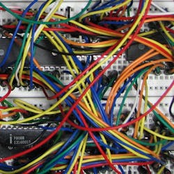
Whether it's the lack of experience of the designer and builder or the OEM thinks it's OK to do it that way to save money or someone is just being lazy, messy control-enclosure wiring and lack of wire labels are just a job done poorly in the world of industrial control systems. When it comes to terminating I/O and power wiring in a control enclosure, there are basic standards that must be followed.
Without terminating the wiring properly, the end user of the control enclosure is destined to suffer a decade or more of a difficult-to-support and troubleshoot control system. To help eliminate this painful future, just about any industrial-equipment user should require suppliers of control systems and control panels to follow some control-panel-wiring best practices. A good source for these wiring practices and much more can be found in NFPA 79: Electrical Standard for Industrial Machinery, 2018 edition.
When designing a control system, standards must be followed. It's important to note that any control-system designer who wants to know the details on how to design a control system should purchase and read the latest edition of NFPA 79. While it's just one of many standards automation engineers should use, NFPA 79 is a must-have for any machine builder, OEM, system integrator or any end user with automated machines. It provides control-design standards and how to install electrical equipment properly to protect operators, equipment and facilities from electrical hazards and fire. It includes wiring practices.
Proper I/O termination isn't just where the screw and plate squeeze the wire. It starts in the field and terminates many places within a control enclosure. Routing cables to the enclosure should closely follow the equipment and machine frame. The cable bundles should also be supported and attached to the frame every foot or so.
These field cables need to be protected from damage, and the equipment shouldn't cause any damage. Cable routing provides long-term protection, so don't attach the cables to machine guarding that may be removed. Also, if a damaged sensor cable must be replaced, as part of a bundle of cables, cut all the cable support ties, remove the faulty cable, replace the sensor cable and then reinstall the cable ties while keeping the cables parallel in the bundle, not woven-like.
The rat’s nest may be outside the control enclosure. By not reinstalling the cable ties and just strapping the new cable to the outside of the existing cable bundle or leaving the faulty cable in the bundle, the technician is just creating a mess that only gets worse over time. A poorly done repair, with the excuse that it was quicker, is a worst-case practice. Don't be a hack; take the time and do it right. And there are many more requirements to be met.
Once the field cable enters the enclosure, it must pass through a terminal, or, more precisely, a row of terminals, fused terminals and circuit breakers mounted on a DIN rail—a terminal strip. These terminals must also be suitably sized for the gauge of the wire terminated.
There are very few instances where a terminal, as part of a terminal strip, is not used to connect all field wiring. Field wiring does not attach directly to relays, input/output modules, safety devices and drives; it passes through a terminal first.
Each cable or wire connected to the terminal strip must be labeled to match the electrical schematic. The terminal strip should also have a label on the back panel, such as TS1 (terminal strip 1). Each terminal should also be labeled to match the wire number or given a terminal number as documented in a complete, as-built schematic.
Every wire, cable and terminal must be labeled and match the schematic. While wiring inside a washer or dryer in a laundry room may not be, control systems for equipment and machines on the factory floor must be labeled and terminated as documented.
I/O termination can be through a variety of terminals, terminal breakout boards or directly to the controller I/O, but only if the I/O is designed for that purpose, such as some distributed I/O. Terminals come in single level, double level, triple level and others.
Single-level terminals work well for miscellaneous terminations within the enclosure and some power distribution. Double-level terminals work well to terminate discrete output signals with one level for the output and one level for a bussed common. It's also a good way to distribute 24 Vdc power. Triple-level terminals work well to terminate discrete input signals, providing an input terminal and terminals for +24 Vdc and 24 Vdc common, often needed for sensors.
Analog I/O termination benefits from multi-level terminals, up to five levels, to address needs for loop-powered or self-powered transmitters and cable shields, which must also be terminated.
Some final notes on eliminating the rat’s nest: Terminal strips usually are surrounded by wire duct (wireway) to manage the wires. Wires do not pass over the top of terminal strips; they go around, using the wireway. And in no cases are splices, wire nuts or solder connections allowed to stretch a wire in the duct—add a connector.
ALSO READ: Step up the technology in machine control
About the Author

Dave Perkon
Technical Editor
Dave Perkon is contributing editor for Control Design. He has engineered and managed automation projects for Fortune 500 companies in the medical, automotive, semiconductor, defense and solar industries.


