Industrial engineers, designers and panel builders are facing the increasingly difficult challenge to design cost-effective but high-performing panel systems that can be installed and used all over the world. Market demands include reducing the size of installations and machines, regulating energy consumption, adapting to design changes and increasing productivity. However, designers are able to optimize the production of an electrical cabinet by following a streamlined design process in the implementation of terminal blocks.
Terminal blocks are among the smallest components that make up a cabinet, but in their apparent simplicity they are vital for the successful implementation of an installation. The implementation of terminal blocks during the design of an electrical cabinet can be broken down into seven important stages during which designers will have to use reliable and efficient resources to best define their installation.
Phase 1: study, design and planning
The “study, design and planning” phase is when the engineer will make the selection of the products, the design and the layout of the electrical panel. This first step is crucial for a smooth project. The study portion includes considering the physical needs, such as internal installation, dimension and size, as well as electrical sizing of equipment, protection and conductors. This phase generally calls for the skills of engineers or specialized technicians to select the best components and implement them using dedicated software. High-performance tools exist to facilitate the selection of products and facilitate their electrical (electrical CAD systems) or physical (3-D CAD) implementation.
Designers and builders should utilize tools and software during the panel design and build process. With advanced building software, customers can build a complete assembly, rather than laying one to one terminal blocks.
With virtual design software and tools, customers have the ability to make the drawing or mockup of the system and order it in a few single steps.
Phase 2: installation
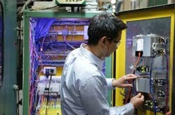
Installation is implemented by the cable fitters and electricians on the panel build project. This requires an accurate interpretation of the electrical diagram, product knowledge and efficient time management. This phase is critical regarding the loss of time, which can quickly weigh on the cost of a project—difficult assembly, errors, tedious installation of accessories or too many accessories.
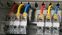
Figure 1: Choosing the right connection technologies is very important in panel design.
Terminal blocks need to be installed on the rail; usually it’s a piece of a metal rail that is mounted on the frame of the panel, where the panel builder is snapping on the terminal blocks. Here, the design of the terminal blocks becomes important to make sure there isn’t time lost in handling the products.
Choosing products with ergonomic function and accessories can save a significant amount of time in this stage of manufacturing.
Phase 3: connection
Choosing the right connection technologies is very important in panel design (Figure 1). This is often a big point of discussion for customers as they’re related to the habits, the locations they’re used and the environments they’ll be in. Connection technologies used in terminal blocks have undergone significant technological developments in recent years and can be a significant source of savings.
Other than the screw clamp, which is the record technology still being used frequently, you have screwless connections such as push-in and spring technologies. Insulation displacement connection (IDC) is another option; there is no preparation of the wire. The wire is pushed by a tool that can pierce the insulation and make contact.
Phase 4: power distribution
One of the main rules in the creation of a cabinet is to respect the installation of electrical devices in the cabinet. The equipment inside the cabinet can thus be grouped into large groups, which are the power components—main protection, splitters—that take charge of the distribution of the power supply for all the equipment in the panel. Each group can then be subdivided into sub-groups. If the control part is often well-mastered, the power distribution can be further optimized by using, for example, modular splitters offering greater flexibility of use.
At some point, you need to disrupt the power, and there is equipment within the panel that needs to do that. To split the main power to the different circuits, modular splitters called power distribution blocks can do that efficiently in all power terminations.
Phase 5: identification and tracking
Identification and marking are important in all phases of the project. At the very beginning, it makes it easier to locate components in the cabinet. During the wiring phase, the markers installed on the components, and mainly the terminal blocks, help the cable technician to quickly make the link between the electrical diagram and the installation in the cabinet. Therefore, users must pay special attention to it, especially when the installations use hundreds of components. Not only must each component of the panel be marked, but the syntax of the marks must make sense, and they must be placed so that each one is clearly visible.
You need to have identifications where you can put a certain number of digits to be quite precise. Many times, there are changes. With many terminal blocks, you need to print all your markers before starting the wiring. Others offer a flat surface so you can take a pen and write the marker directly or use a sticker. Then changes can be made, and, when finished, the final markers can be printed.
Phase 6: grounding and protection
Grounding and protection and all the equipment that it constitutes are essential to ensure the safety of the user and the equipment. The user needs to take special care to ensure the distance between the different equipment and a good earthing (low impedance). The entire chain, from the equipment inside the cabinet to the earthing bar, must comply with precise normative rules in order to ensure safety in the event of a fault on the installation.
Users need to comply with international and local standards to respect in terms of grounding and protection, either through ground blocks or fuse protection, which are protecting against fire and short circuits.
Also read: Environment Could Affect Choice of Terminal Blocks or Their Enclosures
Phase 7: Test and maintenance
Testing and maintenance can be carried out at any time of a project, but they are mainly used in the last phase. Testing means the functional verification of an equipment or installation. For a panel builder, the test operations will be carried out at the end of production before delivery to the customer with a verification of the conformity of the wiring with the drawings, the insulation of the equipment and the correct identification of equipment and circuits, as well as earthing. Large installation tests, or acceptance tests, can be carried out by the customer at the manufacturer’s premises in order to verify the correct functioning of an installation before delivery and installation on site.
Maintenance operations are carried out on the installations in operation and often by the customers themselves. The functions used in this case are the measurement of electrical quantities—current voltage, isolation of circuits (dielectric test) for troubleshooting and fault finding on the installation.
Vincent Ménager is marketing and application specialist at TE Connectivity.
About the Author
Vincent Ménager
TE Connectivity

Leaders relevant to this article:


