Stop EMI from ruining your day and your system performance
Electromagnetic interference (EMI) is the generic term describing a situation where an electrical disturbance generated by electrical or electronic equipment causes an undesirable response to another system. The origin could also be a natural phenomenon such as electrostatic discharge (ESD) or lightning strokes. It can also be man-made from radio transmitters and emissions from digital circuits.
The effect may range from a mere nuisance to a catastrophic failure, with associated financial losses and/or possibly human casualties. Electromagnetic compatibility (EMC) is just the opposite: EMI being the disease, and EMC is the cure. EMC is the discipline of analyzing, preventing or fixing interference problems.
More detailed EMI/EMC information will be offered during the EMC by Your Design Seminar/Workshop, Oct. 4-6 in Northbrook, Illinois. The seminar and workshop will be taught by Donald L. Sweeney, Roger Swanberg and Tim Lusha of D.L.S. Electronic Systems, as well as guest lecturer Michel Mardiguian, author of the EMC design textbook, Controlling Radiated Emissions by Design. More information is available at www.dlsemc.com. The seminars will also be offered in April 2017.
EMI has existed ever since our modern societies started using electricity for transportation, domestic and industrial power, and transmitting intelligence—mostly using telecommunications and radio. In the early days of radio frequency (RF) engineering, many EMI aspects like receiver selectivity and spurious response, channel separation, high harmonic contents of transmitters and the like were unknown. But rapidly the tremendous growth of electronics and RF applications over the years has made the number of EMI incidents skyrocket in all areas: telephone and telecommunications, air navigation, radio and TV services, as well as mobile radio and cell phones.
In the major industrialized countries, RF regulating agencies and private industry decided that the days of empirical approaches and EMI gurus were numbered and that a logical strategy was badly needed. EMC was born, not as a new science, but as a multifaceted discipline, where EMI can be anticipated, simulated and prevented by proper design techniques. Progressively, the essential aspects such as source and victim dichotomy, coupling mechanisms and the like were set forth, along with specific components, instrumentation and measurement techniques.
A measure of this invisible EMI threat is given by the following examples of EMI incidents that occurred worldwide in the period where many EMC regulations were not yet applied. The full list of reported incidents, not to mention the unreported ones because they were not publicized, would amount to an impressive pile of reports.
Figure 1: In 1967, a fire broke out on the USS Forrestal, an aircraft carrier, when an electrical glitch caused a missile to launch, causing 134 deaths and $72 million in damage.
EMI manifests itself in all degrees, from simple nuisances such as:
- 70,000 claims/year (United States) for jammed public radio and TV reception
- remote-controlled garage doors or car locking devices jammed by nearby airport radars
- surveillance cameras jammed by nearby variable speed motor drives
- cash registers and electronic weighing machines in food stores displaying wrong figures because of ESD
- pumps in gas stations displaying wrong price when drivers were using their radios
to catastrophic ones, such as:
- medical monitoring devices (ECG, EKG, blood analyzers, infusion pumps) delivering wrong values when hospital or emergency-medical-service personnel were using portable transmitters or paging devices nearby
- 30-m-high crane dropping its load in a harbor when dockworkers were using their walkie-talkies
- six ferries crashing into piers because the propeller pitch controls were interfered with by local radio-transmitters
- 134 deaths (seamen and pilots) and $72 million damage due to a radar beam unexpectedly firing a missile on the deck of an aircraft carrier, USS Forrestal, during the Vietnam War (Figure 1).
Source-and-victim concept
Given the complexity of the interactions between the many elements and parameters when EMI is involved, a very clear and simple way for addressing the who-does-what of an EMI situation is the source-and-victim concept that sees an EMI problem as a theater act with three players:
- the source of EMI, which can be a natural event (ESD) or from a man-made device such as intentionally generated high frequency (authorized RF transmitters); it can also be a byproduct of its operation such as digital circuits and switch mode power supplies
- the victim of EMI, which can be any analog or digital circuit whose low-level input can be activated, damaged or disrupted by undesired signals (EMI)
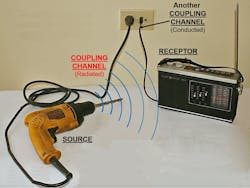
- the coupling path between source and victim, which can be a conducted path through wires, a radiated path through air or something in-between such as cable-to-cable capacitive and magnetic crosstalk.
Figure 2: Eliminate an interference problem by acting on one or several of the three actors, whichever is available for changes, at a reasonable cost.
The combination of source, coupling path air or power wires and victim (radio receiver) is the basis for an overall understanding of EMI and is the key to EMI control in order to reach a satisfactory level of EMC (Figure 2). One can eliminate an interference problem by acting on one or several of the three actors, whichever is available for changes, at a reasonable cost.
Acting on the source: This of course is not feasible for natural events such as ESD and lightning, so in general only non-intentional, fortuitous RF sources can be modified to reduce their undesired RF emissions. Most common examples are digital circuits, switch-mode power supplies and even radio transmitters. Today this is handled through worldwide regulatory emission requirements.
Making the victim circuit less vulnerable: This carries the constraint that the essential characteristics of this circuit such as detection level, bandwidth or time constant remain unchanged. Therefore this option has often a very limited range.
Acting on the source-to-victim coupling path: This is where the designer has the largest choice of solutions: shielding, filtering, grounding, physical separation or orientation and loop area reduction . Thus, a sound approach will take EMC into account from the original concept to the design stage.
Another interesting side of the source-and-victim concept is that it is perfectly reversible (reciprocity). The mechanisms that could cause the circuit to be a victim are the same mechanisms that could make it a potential source of interference.
The importance of frequency
Practically all coupling mechanisms that are conveying the source emissions to the victim’s input are frequency dependent: that is, as frequency increases, the coupling coefficient increases. In some cases, it may even be aggravated at the frequency squared.
A quick example can give a measure of this aspect of frequency. Assume you have a long wire carrying a constant-value ac current of 1 A. At 10 cm distance from a 100-cm2 nearby loop, this 1-A current will induce, by magnetic coupling:
- at 50 Hz; 6.3 µV
- at 100 kHz; 12.6 mV
- at 10 MHz; 1.26 V.
4 parts of the EMC picture
Based on our source-and-victim principle, the reduction of EMI situations to a tolerable level will be secured by controlling the EMC performance of the equipment before it is put on the market, which can be verified by the following EMC tests.
The conducted emissions (CE) and the radiated emissions (RE) levels of the equipment need to be controlled when they are potential sources of interference to nearby systems or to the outside world. This is accomplished by measuring with proper instrumentation the amplitude of high-frequency noise that is seen as conducted and radiated emissions. Levels are then compared to the applicable regulatory limit to determine compliance. These regulatory norms have been devised to protect users of the civilian and/or military radio spectrum. Conducted emissions are measured on external power wires and telecommunication cables. Radiated emissions from the equipment under test are measured with calibrated antennas and special receivers.
Figure 3: Most products are tested to ESD, radiated RF, fast electrical transients, lightning, conducted RF, magnetic radiated and power line variations. (Source: D.L.S. Electronic Systems)
The conducted susceptibility (CS) and radiated susceptibility (RS) levels of the equipment are determined when confronted by the many EMI threats which potentially exist in their surrounding environment. This is accomplished by simulating and exposing the product and its enclosure to CS or RS disturbances. During this testing, the equipment is monitored, confirming that it is still functioning properly and meeting its design criteria. Conducted susceptibility is tested by injecting calibrated high-frequency (HF) and transient pulses on external power wires and communication cables. Radiated susceptibility is tested by illuminating the equipment under test with strong RF fields in an EMC test chamber so as not to interfere with the outside world (Figure 3).
When referring to industrial products, the term “immunity,” a product’s ability to not have an adverse response to disturbances, is more often used than the term “susceptibility,” which is an adverse response to disturbances. “Immunity” is a term introduced by the European community.
External vs. internal EMI/EMC
There is an important difference between an interference that is caused by or suffered from the external environment and interference occurring inside the equipment where the product is disrupting itself, or self-jamming.
Internal EMC is a basic condition for making sure that there is no internal source-to-victim combination that can create a performance degradation or upset. It is a designer’s responsibility to first check that the internal EMC is correctly addressed; otherwise the equipment will not work properly. Satisfying internal-system EMC is the prime and selfish goal of any designer who is concerned with moving and operational products through the assembly line.
External EMC levels are dictated by regulatory agencies such as the FCC, the European community or procurement specifications. It actually is imperative for the system integrator to understand at the very beginning of the design cycle which regulatory requirements are going to be dictated for the product. In the early days of testing, we typically had just the FCC's requirements, which were only conducted and radiated emissions starting at 450 kHz and going to 1 GHz.
Today the FCC and European requirements test conducted and radiated emissions beyond 1 GHz to possibly 40 GHz, and European requirements also require immunity (susceptibility) testing. These tests impose much harsher requirements for both filtering and shielding than was initially required for the FCC. If you are designing your equipment to eventually go to the European Union (EU), then you really want to make sure that you've included the more severe immunity requirements.
If you initially plan not to ship your product to the EU, you may still want to test to the more severe immunity requirements in case the opportunity to sell in Europe arises at a later date. To update your equipment later to the more severe requirements could be cost-prohibitive.
The challenge for machine builders/system integrators
Designers who are integrating modules in a large frame have an additional challenge. Assuming they have to integrate subassemblies into a system that must comply with a certain set of EMC requirements, they may face anything from the best- to worst-case arrangements.
A, B, C modules have been tested and found individually compliant with the prescribed EMC specifications. It is reasonable to expect that A + B + C functioning together will also be compliant. The system designer may or may not be exempted from retesting the entire system by the procurement requirements. But remember, all international regulatory agencies specify that a system must not interfere with communications. Therefore the integrator is still responsible for the overall EMC compliance.
Simply put, almost anywhere in the world that the product is placed into service, the product will be expected to not cause interference with radio communications and not be interfered with by any anticipated interference in its intended environment. It would be prudent to ask for the actual EMC test results of the individual items. If one or more are close to the limits, with no margin, the mere fact of combining them together with additional interconnecting cables and connectors may deteriorate the EMC level. The rule of thumb is two items with identical emissions when combined can have an increase in emissions of 20 log 2 = 6 dB.
None or not all of the A, B, C modules have been tested or characterized. Since these subassemblies are already designed, there may not be time or space to improve the individual EMC performance. Therefore it will be up to the integrator to provide the necessary add-on hardware. If only one or very few modules are noncompliant, some piggy-back solutions can be added such as filtered adapters on I/O connectors, ferrite sleeves on cables, shielded cables and dedicated power line filters. If all or the majority of the modules are noncompliant, it may make more sense economically to consider the host frame as the EMI final barrier and treat it accordingly by adding:
- filtered power input and I/O connectors
- shielded cables at least for signal lines
- shielded ventilation openings and displays
- conductive gaskets on cabinet doors and maintenance panels.
When implementing these improvements it is important to consider the following design rules:
- filtered power input and I/O connectors
- shielded cables
- shielded ventilation openings
- conductive gaskets
- product testing.
Figure 4: Add a simple homemade, single pole filter to individual signal lines.
Figure 5: Commercial filters are available. Quick-fix filtering can be added in series with the cable. (Source: D.L.S. Electronic Systems)
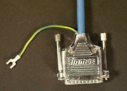
Figure 6: A pigtail can compromise emissions, as well as susceptibility, on shielded cables.
Filtered power input and I/O connectors: Care must be used in order not to distort the intended signal wave form while removing the offending EMI frequencies with filters. In 2009, the late Dr. Clayton R. Paul—author, educator and IEEE life fellow— helped us to determine we need to keep the fifth harmonic, which gives 7% distortion of the waveform, which should be sufficient for most applications.
Also read: Five common problems with wiring and connections
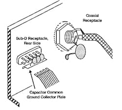
Filters need to be terminated to ground with a minimum termination length. One can add a simple homemade single-pole filter to individual signal lines—“single-pole” meaning one element, such as one capacitor or inductor (Figure 4).
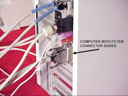
Commercial filters are available to filter many wires simultaneously. A commercial filter can be added to all 25 pins of the connector. Here the length-to-ground leads are controlled to almost 0 inches because they use surface-mount capacitors (Figure 5).
Commercial power line filters can be readily purchased. Make sure that they’re installed correctly, ensuring the input and output wires to the filter don’t come close to each other, thus negating the filter's purpose.
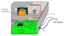
Shielded cables: Shielded cables can be added to external signal cables. It’s imperative that shields on the cables be terminated properly in order to function as intended and that noise isn’t picked up by the termination. A poor termination may result in a pigtail (Figure 6). A pigtail can compromise emissions, as well as susceptibility on shielded cables. Noise can be picked up by a single wire leaving a shielded box, which is used as a cabinet for the system being designed. If these cables are not filtered or shielded and properly terminated, they will radiate emissions outside of the enclosure (Figure 7).
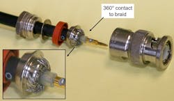
The shield of a coaxial cable can be terminated to the connector with 360° termination (Figure 8). If the shield were just terminated to the cabinet with a single braid, it would be considered a pigtail, which you don't want.
Shielded ventilation openings: These can be a simple screen wire, or they can be made as a ventilated shield. Any ventilated shield should be terminated around its entire periphery to avoid RF leakage (Figure 9).
If required, special windows can be added allowing visual transmission while preventing the RF fields from entering or leaving. The termination requirements are the same as they are for shielded ventilation openings.
Conductive gaskets: When adding these on cabinet doors and maintenance panels, care must be given to avoid painted surfaces. Gasketing can help to seal doors and seams.
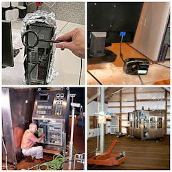
Product testing: Lastly, it would also be prudent for the integrator to consider testing the product as early as possible in order to avoid any delays in getting the product to market. There are many examples of the various types of testing, from problem-solving to final accreditation (Figure 10).
Figure 7: If cables are not filtered or shielded and properly terminated, they will radiate emissions outside of the enclosure.
Figure 8: Proper termination of a coaxial cable with 360° shield termination avoids pigtail potential.
Figure 9: Ventilation can be added in many ways, but any ventilated shield should be terminated around its entire periphery to avoid RF leakage.
Figure 10: There are many examples of the various types of testing: simple test using the magnetic probe to find RF leakage from a cabinet; troubleshooting by checking emissions on a cable using a current clamp to monitor common mode currents; problem solving a large control system; and final testing for emissions of a large industrial device. (Source: D.L.S. Electronic Systems)
Summary
As we can see, system integrators and control designers must give a lot of consideration to EMI/EMC. If not taken into account early in the design process, the product can be late to market or, even worse, fail in the field—failures as simple as nuisance failures or catastrophic incidences where lives can be lost.
It's a good idea to get your product into the test lab early to find any problems that have not been anticipated. The earlier in the design process EMC/EMI is taken into account, the greater your chances of complying with the requirements and avoiding costly fixes.
If all of the EMI/EMC design ideas are implemented, there is a good probability of your product meeting its requirements and being shipped on time.


