One of the problems with software development is that the increase in efficiency is very low. No Moore’s Law here, no doubling of the efficiency every 18 months. And it is even worse: With increasing functionality, the complexity increases exponentially. To solve this one needs modern software development tools and modern development methodologies.
Part of a modern software-development methodology is creating reusable components, called function blocks, which contain part of the application software functionality. This process is called encapsulation. The next step is to integrate these tested and documented components in your own library, from which everybody in and outside your organization can make use and in this way create extended application software faster and with fewer errors.
ALSO READ: PLCopen releases 3 new specifications
Edge-triggered vs. level-controlled
Basically, there are two types of function blocks:
- those that are initialized (started) at a rising input and stay active until finalized or aborted
- those that are active as long as the corresponding input is high.
The first are called edge-triggered, and the second are called level-controlled. An example of edge-triggered functionality is a move-to-position command which, after being initialized via the input, “Execute,” runs until finalized. An example of a level-triggered functionality is a PowerOn function, where the power is switched on as long as the relevant input (Enable) is set. Notice that the Enable input pairs with Valid output, and that Execute pairs with Done.
Sometimes it is important to choose a level-controlled model rather than an edge-triggered model. For the detection of a rising edge in a function block, two PLC cycles are necessary. Thus, if the requirement is to be able to process a new value in each cycle, an edge-triggered model cannot serve as a solution. In this case, a level-controlled function block model is the preferred way to implement the required functionality.
The basic function block is the Etrig. This is the edge-triggered functionality in its simplest form with only an Execute as input, both in textual and in graphical representation (Figure 1).
Figure 1: The basic function block is the Etrig, the edge-triggered functionality in its simplest form with only an Execute as input, both in textual and in graphical representation.
The corresponding state diagram consists of the Dormant, Executing and Done, linked to Resetting and back to Dormant for the normal behavior, and via Error for the irregular behavior. For implementation, the state diagram can be easily converted to sequential function chart (SFC) or structured text (ST). Examples of this are included in the specification (Figure 2).
Figure 2: The state diagram can be converted to sequential function chart or structured text.
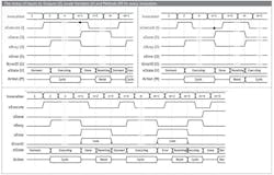
The corresponding timing diagrams for Etrig show the behavior in case of an error (Figure 3).
Figure 3: The third timing diagram shows the behavior in case of an error
In addition, one can add the aborting functionality to abort the process, which includes additional states, Aborting and Aborted (Figure 4). This state diagram also can be converted to SFC or ST.
Figure 4: The aborting functionality can be added to abort the process.
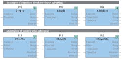
On top of the abort functionality, or even without this functionality, one can add timers to make the functionality more robust (Figure 5). There are three options for timers:
- TimeOut (To)—the overall operating time of the defined operation should be lower than the time (in µs) as specified by the input value udiTimeOut
- TimeLimit (Tl)—the time limit is set so the operation stays within the cycle time. In that way, a longer operation can be divided over several cycles
- the combination of them both (TlTo).
Figure 5: On top of the abort functionality, or even without this functionality, one can add timers to make the functionality more robust.
What does udiTimeLimit do? A function block could, for example, complete a complex task in a loop. The larger the task is, the more time that is consumed in the current task of this function block. The udiTimeLimit parameter can define how much time per invocation is permitted for consumption in the respective function block.
What does udiTimeOut do? When processing its cycle action, a function block can be forced to wait for an external event. It can do this in an internal loop (BusyWait), or it can check in each cycle whether its task can be completed in full. The udiTimeOut parameter can define then how much time is permitted for consumption in the xBusy state.
Level-controlled function blocks
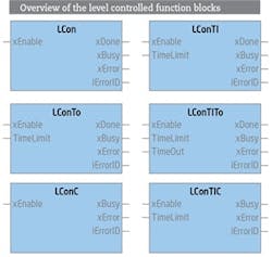
For level-controlled functionalities, a similar set can be identified with similar states (Figure 6). Adding the timers Time Out (To) and Time Limit (Tl) and the combination (TlTo) is similar.
Figure 6: Similar to edge-triggered functionalities, level-controlled can be identified.
However, there are two additional blocks for continuous behavior, meaning it doesn’t stop, so there is no Done state: LConC for Continuous Behavior and LConTlC, including the time limit (Figure 7).
Figure 7: This is an overview of the level-controlled function blocks.
Function-block data sheets
Included in the specification itself are the data sheets for all of the listed function blocks. This includes the state chart, the implementation and, for the edge-triggered function blocks, the timing diagrams.
Also, for the LCon functionality, an example of the corresponding ST code is included with object orientation. In the appendix is an ST code example for the ETrigATlTo function block, according to IEC 61131–3, 2nd Edition, meaning no object orientation added.
With the document, “Creating PLCopen Compliant Libraries,” the organization shows how users can create their own libraries within the PLCopen concept. This concept includes both level- and edge-controlled functionalities, which are extended by aborting and timer functionalities. To complete this specification, examples in ST are shown, both in the classical and in the object-oriented approach.
Creating PLCopen-compliant libraries
PLCopen specified kinds of reusable components already for many application areas, such as the function blocks for motion control, safety and communication. Now PLCopen wants to reach out to software engineers who create their own libraries at machine builders and system integrators. To ease the development of user libraries, PLCopen, together with its members, created guidelines on how to create PLCopen-compliant function blocks.
About the Author
Eelco van der Wal
PLCopen

Leaders relevant to this article:


