From manufacturing and lab diagnostics to farming and communications, motion control is vital. It requires the precise manipulation of the physical world to optimize a process. This can include anything from guiding a tractor along rows of a crop to controlling the motion of a robotic arm. The 80/20 rule applies to motion control; with a basic understanding of many fields a motion control professional can be effective and offer focused solutions to the applications they address. Motion-control basics include key components with critical roles in the process.
Mechanical components
In addition to manufacturer’s specifications, a general understanding of each technology will go a long way in getting to a solution that not only meets the performance requirements for motion, but also the size constraints of the application, as well as a bearable cost.
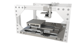
For example, on applications that require linear motion, a direct-drive linear motor offers exciting performance capabilities but may also be outside of the allowable budget. When considering performance criteria, if speed is valued over force and precision, a belt-driven stage will be a lower-cost alternative. If force is critical, a ball screw can offer advantages over a belt-and-pulley solution. If force is critical, but the application has a vertical orientation, and there’s no space for an external brake, then a low helix lead screw that does not backdrive may be more appropriate. If the application needs speed, but has a high inertial load, control is improved by adding a gear reduction between the motor and belt-driven table to reduce the reflected inertia back to the motor.
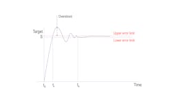
Once these items are reviewed, there is still component compliance to consider, which can act as short-term energy storage and reduce the system’s bandwidth in the form of higher settling times. A deep understanding of the physics of motion and the governing equations for each mechanical component is needed to quickly put together a viable solution for the application in question.
Motors
Brushed dc motors are relatively simple and inexpensive, making them a popular choice for low-cost applications. However, they are not as precise as other types of motors and can suffer from brush wear over time, degrading performance.
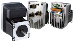
Stepper motors are more precise than brushed dc motors and are often used in applications that require accurate positioning. They work by rotating a fixed number of degrees with each electrical pulse they receive, making them ideal for applications where precise control is necessary. While repeatability and precision are good, they are speed-limited and have lower efficiency than servo motors when using open-loop control.
Servo motors are a bit of a misnomer because a servo motor is really a servo system architecture. It requires not only the motor, but also a feedback device and specific drive control. It is the most precise type of motor and is typically used in high-performance applications. The feedback sensor is used to monitor the motor's position, allowing it to adjust the position, speed and torque as necessary to maintain the desired motion. This is the most complex of the three but generally offers the highest performance.
Feedback sensors
Feedback sensors are used in motion control-systems to monitor the position, speed and acceleration of the motor and load. This information is then fed back to the controller, which, when using a servo system architecture, allows it to adjust the motor's speed and torque on the fly to maintain the desired motion.
Alternatively, feedback sensors can be used for position correction or flagging an error where action can be taken by the controller apart from full servo control of the system.
The most common type of feedback sensor used in motion control systems is the encoder. Encoders are devices that convert mechanical motion into an electrical signal that can be used by the controller.
There are two types of encoders commonly used in motion control systems: incremental and absolute. They come in different form factors to address the needs of the application, linear and rotary being examples.
In addition to form factor, encoders are available in many different technologies, including optical, magnetic and inductive. Each technology has its own set of strengths and weaknesses that will help guide the appropriate selection for the application. Common characteristics include resolution, accuracy, communications protocol and environmental sensitivity, to name a few.
Encoders can also be used to improve functions other than motion in a system. For example, in high-end imaging applications, a linear encoder may be used to trigger an image capture at preset intervals allowing for reliable inspection of part defects, molecular diagnostics and semiconductor-wafer integrity.
Drives
Drives in motion-control systems were once only used to amplify the signal sent by a higher-level controller. In this sense, the basic function is to handle the high electrical power demands of the motor, both current and voltage, to meet the applications needs.
Brushed dc drives are typically a basic solution and are used to control the speed of dc brushed motors. They work by adjusting the voltage and regulating the current supplied to the motor. These can have a basic interface, such as an analog voltage input that acts as a proportional control for the motor’s speed.
Stepper drives are used to control the speed and position of stepper motors. They have three basic options:
• constant voltage, also known as L/R
• constant current, also known as a chopper drive
• closed-looped control.
The L/R is the most basic option and offers the lowest level of performance. In this case, the supply voltage of the drive is matched to the coil-winding voltage of the motor. As with any motor, the level of torque achieved is directly proportional to the amount of current passing through the windings. The motor coil will have some level of inductance which will limit the rate of rise in current in the winding and thus the torque of the motor. As the speed of the motor increases, the current is choked out due to the inductive property of the windings and thus torque is reduced.
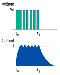
A chopper drive improves performance over an L/R drive by configuring the drive to operate at the root-mean-square (RMS) current rating of the motor’s winding. The method for maintaining the proper motor phase current across the speed range of the motor is to rapidly turn on and off a relatively high source voltage, typically eight times larger than the motor’s winding voltage rating. This causes the transient response of current in the windings to have a steep rise.
Closed-loop stepper drives have similar requirements to servo drives, so we’ll group them together, but understand that servo drives running a servo motor are generally controlling a three-phase brushless dc (BLDC) motor, where a closed-loop stepper drive is controlling a two-phase stepper motor.
Unlike the brushed dc and open-loop stepper-motor drives, a servo drive will require a feedback sensor, most commonly an encoder. The control scheme is fundamentally different from the other drives because the drive is controlling the motor based on the error between the commanded and the actual position of the motor.
A feedback sensor is required to measure the actual position of the motor. The drive is constantly trying to reduce this error by controlling the current to the coils via PWM to close the gap between the commanded and actual values. The response to the error is set via control gains.
Proportional-integral-derivative (PID) control is a common control-gain scheme. Varying the control gains is known as tuning and has a massive impact on the system’s performance. The same mechanical system can be tuned for various application needs. For example, in high-throughput applications, such as is common in factory automation, the time to complete the move may be critical, so variation during the move can be tolerated while duration of the move is minimized.
Controllers
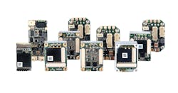
Controllers are the brains of a motion-control system. They monitor the state of each axis of motion, send commands to the drive to orchestrate proper motion execution and in many cases coordinate the entire function of the system or machine, including error handling, safety and the human-machine interface (HMI).
There are several types of controllers commonly used in motion-control systems, including programmable logic controllers (PLCs), PCs and dedicated motion controllers. Controllers build the motion profile and segment it into smaller sections that are sent to the drive of each axis via a communications bus such as EtherCAT, Profinet or CANopen, for example. This allows the controller to manage true coordinated motion between multiple axes, which enables complex three-dimensional control in physical space, while also allowing for higher throughput and mitigating the risk of collision between axes.
This is possible because of deterministic network protocols that ensure the command will reach the intended axis within a specific time. Network solutions also enable decentralized control topologies.
A multidisciplinary understanding allows motion-control professionals to be effective and efficient in developing solutions for the most demanding applications. That’s one reason why A3—Association for Advancing Automation—has compiled a course led by industry experts to cover the broad topic of motion control and give attendees the opportunity to expedite their motion control understanding and effectiveness.
There’s no shortage of processes being automated, and, while AI, deep learning and advanced vision system algorithms are enabling automation in new ways, there will always be a need to connect software applications to the physical world.
Register for the conference at Automate Registration.
