Communication simplifies test system design
In manufacturing, it’s necessary to ensure that parts or subsystems meet performance criteria before they are sold or used in larger systems. This type of testing can range from very simple to extremely complex. However, the complexity of the test doesn’t always correlate with how routine it may be to accomplish. For instance, as part of a larger assembly, one of my customers manufactured an array of small pushbutton switches. Before the parts were sent to the next step in the process, specific tests for functional operation had to be performed. One way to do it would be to have workers push all the buttons while monitoring an indicator, but that is extremely monotonous work. Furthermore, the customer was concerned that defects might be missed due to human error.
Testing required
The customer wanted to create an automated test fixture that would be capable of testing the switches better, faster and more reliably than human testing would. In addition, it wanted the ability to make minor changes to the testing parameters to accommodate future changes in the product.
The switch operation was tested to ensure the contacts on the switch closed after a predetermined press distance. The force used to press the button was also tested to confirm it did not exceed a setpoint limit. Finally, testing was performed to ensure that the contacts opened when the button was released. For product safety during the test cycle, it was necessary to limit the force to assure the system wouldn’t break any part of the assembly if pushed too hard. This was needed in case a switch had been mounted incorrectly.
There was a possibility that the testing parameters might change in the future, and the customer wanted to plan for these changes. These included the push force, distance to push and the physical positions of the buttons in the array. In other words, the number of buttons in an individual array or the number of button arrays may change in the future, and the customer needed to be prepared.
By the time the customer engaged us, its engineering team had developed a pretty solid concept that involved plugging multiple switch arrays into a fixture electrically connected to a programmable logic controller (PLC). Through the fixture, every button was connected to an input point on the PLC, so each button pressed would turn on unique input.
The PLC would command the automation to move to a button’s x-y coordinate position and then push the button while monitoring that both the button-pushing mechanism and the button operated correctly closing the switch contact at the proper push distance. This way, the customer could reliably record a pass-or-fail result for every single button.
A 3-axis motion solution
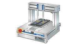
Using electric, motor-driven actuators and motion controllers from one of our vendors, Intelligent Actuator (IAI), I helped the customer specify three very simple motor-driven ball-screw actuators and appropriate controllers (Figure 1). Two of the actuators would be for the x and y movement that would position the third small, low operating force electric actuator over each button where it then moved in the z direction to push the buttons.
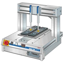
Figure 1: Motor-driven actuators and motion controllers were designed and packaged into a simple and capable test system.
(Source: Intelligent Actuator)
To keep costs down, each axis had its own simple driver/indexing controller. Typically, the simple driver/indexing controllers can be controlled using digital I/O to recall preprogrammed positions and command movement to them, but, with three controllers, that would be a lot of wiring to design, implement and troubleshoot. The customer’s PLC had the capability of using EtherNet/IP, an industrial Ethernet fieldbus that allows devices from different vendors to communicate with each other. The use of EtherNet/IP had the advantage of simplifying the connection to the PLC, reducing the amount of programming that needed to be done in each controller, and providing more detailed feedback from the controllers for the PLC to capture.
The controllers’ connection to the PLC used common Ethernet cables and unmanaged Ethernet switches with no I/O wiring. This networked connection allowed the PLC to send all the target-position data to the controllers before each move, so there was no need to pre-program move data into each controller. This had the added benefit of making it easier to change positions due to product changes. The current position variables and alarm and move completion status bits could all be passed back to the PLC over the network connection. This additional feedback about each move was used by the customer to better error-proof and validate the test.
The z-motion actuator used to push the buttons was a challenge because the test required movement to a predetermined position using a preset push force. If too much push force was required to actuate the button, it would indicate a failed button test. However, it shouldn’t be an alarm or error that would stop further testing. In addition, the actuator movement was less than 25 mm, which is very small for a motor-driven, lead-screw or ball-screw actuator.
The buttons needed about 3 lbf to operate, and the actuator specification was approximately 5 lbf maximum. The motion controller allowed the PLC to define moves that not only had the usual target position, speed and acceleration/deceleration, but also allowed the setting of a maximum push force. All the available motion settings helped to determine good switches from bad. For example, the maximum push force could be set to 3lbf (60% of max) for the button-pressing move. If the target push force was exceeded before the target position, then the PLC would know that the button was defective. At the same time, if the target position was reached but the button contacts didn’t close, as determined by the PLC I/O, the button would be considered defective.
The customer used a PC with SCADA software as the HMI, which included data collection and storage for the test fixture (Figure 2). It also included the graphical tools, device drivers and database needed. The PC communicated with the PLC via Ethernet, which in turn communicated with the motion controllers. The operator could use the PC to enter test-configuration data, which included number of switches and number of cycles per switch, and to start the test. Next, the test results were stored on the PC upon completion. A visual display could indicate the pass/fail status clearly to the operator so that bad parts were easily removed.

Figure 2: The customer used a simple SCADA/HMI software package with all the graphical tools, device drivers and database needed to connect, communicate and operate all the devices.
(Source: Omron Automation Americas)
In the end, the customer was very happy with the way the system worked. The number of button tests completed in a shift increased dramatically, and the reliability of the testing increased. Furthermore, the time to build the controls for the test fixture and the customer learning curve were both reduced because it could use the SCADA software and PLC brand that it was already familiar with because of the EtherNet/IP interface on the Intelligent Actuator controllers.