Modular laser control offers precision and efficiency in industrial manufacturing

Lasers have been used for welding and cutting applications in materials processing for many years. However, laser technology has frequently been considered a specialist area, requiring complex control systems for accurate positioning, as well as significant investment and expertise. Recently, the cost of lasers has decreased, opening this powerful technology up to new applications; even the latest extremely fast ultrashort pulse lasers are now feasible options for machine builders who would typically have used less risky laser setups.
The commoditization of lasers means that system integrators must do more to gain and maintain an advantage, and that positioning and control, as integral parts of any laser system, are important elements of this. The newer technologies work in a slightly different way, so it makes sense that positioning and control also need to be different. The basic ability to fire the laser in the right place has become more challenging, and a simpler approach is even more important than ever, especially for those who are completely new to the technology.
A uniquely modular approach to laser control makes it far easier and faster for system integrators to design and build systems in the first place, whether or not they have previous experience with lasers. The use of industrial control networks such as EtherCAT makes this modular approach even more flexible, as other items, such as sensors or non-motion devices, can be easily incorporated.
Why choose laser processing?
There are many significant advantages to using lasers instead of traditional machining processes; not least is their capacity for much higher throughputs. Lasers are not susceptible to the same wear and tear that can lead to breakdown disruption and costs in mechanical components and are often efficient at processing materials that are otherwise notoriously difficult to deal with.
The fine beams of lasers also give a level of elaborate detail and accuracy that is nearly impossible to create using other methods, which is ideal for applications, such as those generating high aspect ratio holes or other features requiring similar high precision.
High-intensity short pulse lasers, in particular, are incredibly precise. The low thermal energy deposition around the beam of these lasers means there is negligible damage to the surrounding areas.
Lasers can even process below the surface of a material, depending on where the beam focuses. Examples can be commonly found in microelectronics devices, such as light-emitting diodes (LEDs) and flexible displays.
Balancing speed, power and precision
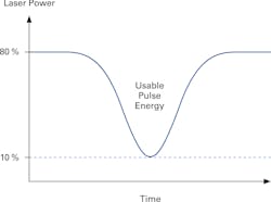
Whatever the application, fast shuttering and accurate firing of laser pulses is essential to ensure consistent, high-quality processing. Precise placement and energy control are crucial for this and can be achieved by linking the automation and motion system directly to the laser output.
It is extremely important to be able to make sure that the laser is focused on the right place for the right amount of time and delivering the right level of power in order to prevent damage to the material or the production of inaccurate parts.
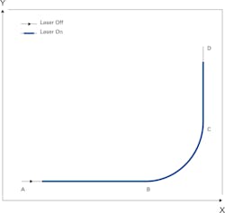
One option is to link laser power to pulse rate and modulation. If the power is fixed, then the motion system will need to run at a constant speed to ensure that the correct level is delivered across the surface. This suits some operations, such as raster scans where the laser is fired following the motion in one direction or during the constant velocity phase between acceleration and deceleration phases.


The problem of HAZ occurs even more frequently with multi-axis systems, simply because of the nonlinear path of corners or arcs. The best analogy is that of a sports car driving around a racing track: when it gets to a corner, it must slow down; otherwise, it wouldn’t be able to follow the racing line and would probably run off the track—the same is true for an xy table.

Linking laser control to speed and position
One of the simplest methods of controlling laser power is to link it to the velocity of the motion path. This can be simply achieved by linking an analog output in the controller to that of the vector speed of the motion path and linking this to the laser power. The analog output is connected to the power input connection on the laser, for example, a 0-10 Vdc range.
Typically, the motion controller will allow you to define a scaling factor so that the maximum output is relative to the maximum power of the laser required for the process; a lower limit may also be set.
It is important to remember that if the motion is badly tuned, jerks may result in bad processing. Poor placement accuracy could also create a bad quality part. This is a simple but effective process, for example, in welding.
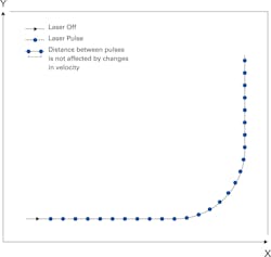
Another approach is to precisely control the laser by pulse placement along the motion path, regardless of the vector velocity. It is also possible to combine these two methods to control scaling of the power output, which overcomes undesired features of the laser electronics or optic path.
There are several technologies available in the industry that can generate such accurate, high-speed, position-based events linked to electronic outputs, for example, laser pulses. Although subtly different from each other, they essentially do the same thing for motion in a single axis.
Some are better suited to galvo-technology; others are more aimed at motorized positioners. With the development of a modular controller, position event generation (PEG) is emerging as a way to link a laser to multi-axis positioning.
Challenges of multiple-axis control
Paths that create three-dimensional trajectories can be created from three or more axes. Examples are simple dual-vector tracking—generated from two axes and widely used for linear xy table contouring, including circles or arcs and straight lines—a linear theta combination for processing tubing, or any combination of linear and rotary stages, for example, producing helical motion for drilling.
Until recently, controlling the motion path for lasers across multiple axes has come with certain limitations relating to performance, speed, practicalities and, not least, higher complexity and costs.
Restricted application, performance and speed
Many of the drives available for precision motion and laser processing have to be predefined, depending on the feedback device used on the stages or the table used in the motion system. Positional feedback means a device that is capable of reading the stage’s position, but also allows the controller to calculate the speed of such a device.
Some motion stages do not use any feedback; they rely on the principle that the commanded motion request equals the actual response.
Typically, feedback systems are either incremental or absolute. Incremental encoders require a reference point or known position when the system starts up, often a homing switch. In comparison, an absolute encoder system has the positional data built into the feedback measurement scale. This positional data is available at startup and therefore removes the step of physically moving the system to a reference device.
Incremental feedback systems
Square-wave encoders provide the system with discrete digital steps of a fixed distance. For example, a square-wave encoder on a rotary motor may output 1,000 steps per revolution; if the rotary motor were driving a 1-mm pitch screw, the system resolution would be 1 mm/1,000, or a 1 µm resolution.
A potential problem with a square-wave encoder occurs when it has a high-count output to obtain resolution and the system also requires high speed. The output frequency could potentially exceed the maximum frequency input of the controller’s feedback circuit, resulting in position loss.
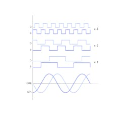
Sine-wave encoders are able to provide much higher resolution with higher-stage speeds because the controller inputs the data at the fundamental frequency of the encoder, which is much lower than the square-wave equivalent. The controller feedback circuit internally subdivides the sine wave into digital steps to produce the internal digital steps; this process is called multiplication.
In practice, a square-wave encoder may start out as a sinusoidal encoder, and the key difference is where the digitalization or multiplication takes place—at the feedback device in the case of a square wave or in the controller.
However, many laser-firing controllers unfortunately cannot use sinusoidal feedback to produce an output that will trigger the laser; their electronics require digital square-wave signals, and this may limit their usability to low-speed systems with high-feedback resolutions or to high-speed systems with low-feedback resolutions.
Multiple feedback in multi-axis systems
Laser-synchronizing technologies use encoder data for single-axis-path motion to trigger, for example, one-to-one firing so that there is a single laser pulse with every millimeter or micron moved. When it comes to multi-axis, for example, pulsing in a circle, the same principle can be applied—data is taken from the individual encoders of each axis and fed into onboard electronics hardware, where the combined vector output is calculated.
This has been the accepted norm for many years, and, in theory, its accuracy comes from the fact that it is based on real-time positional information from the encoders. However, in reality, if the motion system is not adequate in performance, then this approach will produce poor results. For example, a constant-speed circle on an xy table is made up of sinusoidal changes in velocity for each axis. A change in velocity means there must be an acceleration associated with the motion. Acceleration is directly proportional to following error—the difference between the commanded path and the actual path. Therefore, the path will always deviate from what was commanded, and it is the user’s responsibility to ensure the error is below the threshold for the required accuracy. The path may be longer or shorter because of the deviation, which would mean the laser pulsing could be activated at incorrect positions.
Additionally, the electronic circuitry used for processing multiple feedback devices and creating the output vector used for firing can result in a significant delay, or latency, to the output; the more encoders that are tracked, the more dramatically the speed of the output reduces; consequently the data input rate, or tracking, of each feedback is reduced.
Non-incremental, non-direct or non-feedback systems
Firing hardware that requires encoder data obviously cannot be used to generate events for motors that have no feedback—for example, stepper motors. Similarly, they are not appropriate for serial-communication-based absolute encoders. These encoders do not need to be homed when they start up, which can be a significant advantage with regard to safety and convenience for some advanced systems.
Kinematic systems like hexapods are also challenging. The encoder data is not directly linked to the position or motion in a parallel direction or may be a combination of data from multiple axes that requires calculation and so does not generate direct triggering for paths in Cartesian coordinates.
There are very few automation controllers that can handle this level of complexity to ensure that the motion system not only has the correct motion performance, but also the ability to read in and trigger out the encoders used for these applications. With this in mind, users should consider pulsing strategies that do not rely solely on direct feedback.
Whichever method is chosen, the machine builder should always consider the motion performance of the mechanics and controller. Motion systems have other system issues, such as resonances, low bandwidth, under-powered motors or mechanical inadequacies, including accuracy, roll, pitch, yaw, flatness, straightness and stacking areas, that need to be appropriately matched to the system requirements so the work piece or the laser head is in the right place when firing occurs.
Repurposing drive systems
Laser processing puts additional hardware requirements onto an automation system, and the system designer needs to be aware of the input and output needs of connecting a laser to a controller. In theory, every time a system integrator designs a new system with advanced laser control abilities, the system integrator must take the input/output capability of the master controller or the master drive unit into consideration.
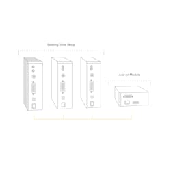
Modular design
A laser control interface (LCI) introduces a way to construct motion systems, based on the EtherCAT industrial network. It does not rely on encoder data and allows drives to select specified axis requirements. This approach offers system integrators, particularly those who are new to the field, a way to expand capabilities when it comes to laser control and gives them the flexibility to add high-performance, multi-axis capabilities only when they are needed, greatly simplifying the system architecture of the drives.
Sharper performance
The ability to use any type of feedback is advantageous from a system integrator’s point of view because it offers the potential to mix axes with or without encoder data, combine incremental and absolute encoders or incorporate kinematic systems that cannot interpret direct output from encoders. This means that a system that uses the right technology to solve the problem can be created.
Simple connectivity
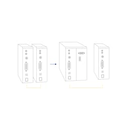
Multi-axis control systems use output encoder pulses from each axis and feed these back to a central location by means of wiring. This sometimes involves complex encoder cables that split the signal between one axis drive and the central controller, adding complexity and wiring to the system build.

No feedback, absolute encoders and kinematic transformation
Using stepper-motor-driven stages for laser control must be undertaken with caution. Open-loop positioning does not provide information when a motor has lost position due to a potential fault, but it does open up the method for lower cost and less demanding motion applications. In addition, there are certain situations where absolute encoders are ideal because they do not require referencing at machine power- up. This can help avoid collisions of stages or parts with obstacles in the machine layout, allowing the system to intelligently create regions where the stages should not enter or provide additional flexibility when unusual or oversized parts need to be processed.
In systems where the three-dimensional coordinate system is made up from complex kinematics or paths created from nonlinear devices such as rotary stages, it is necessary to create motion path data that is not related directly to encoder feedback. The LCI can function without the use of encoder data, so it is ideal for either of these scenarios.
Gantry control
In general, gantries have two motors to move the bottom axes, guided by two encoders directing the base of the system. Other control signals also come from side encoders. However, these encoders may generate different readings, and there is the potential for firing in the wrong place. The risk of this happening increases with wider gantry systems with a long cross axis or high dynamics.

Control options for laser technology
Laser material processing is now a significant aspect of industrial manufacturing, used for tasks ranging from heating for hardening, melting for welding and cladding and the removal of material by drilling and cutting. Many of the technologies would benefit from a system that could synchronize laser pulse control with motion.
For example, high-intensity femtosecond laser processing, which is becoming more common as more industry-proven commercial lasers become available, is considered a cold process because the material being processed does not heat up during the interaction. This type of processing includes texturing of surfaces to decrease reflectivity, provide hydrophobic surfaces or create chemically reactive surfaces. It is of particular interest in the automotive industry, where the push for improved efficiency is driving the reduction of friction of moving components, to lessen the use of lubricant consumables and improve durability.
Another useful property of the cold ablation of high-intensity lasers is the ability to drill clean, small, deep holes in materials without damaging the surrounding material. This technology is now commonly used in the medical industry for fabricating vascular stents, and it has been widely adopted for holes with diameters of microns and a large depth-to-diameter ratio.
Other applications include the dicing of glass that allows the processing of the back of a surface without damaging the front. This application is simply not possible using conventional mechanical diamond-blade dicing techniques.
Micromachining and welding are commonly carried out by nanosecond fiber lasers. Although the fiber laser has longer pulse duration than femtosecond lasers, it can be used with careful control of pulses and processing parameters. In this type of laser processing, the energy is eventually converted into heat that dissipates out of the laser spot, beyond the duration of the laser pulse. Essentially fiber lasers keep costs lower, so, if the process is controlled and the results are suitable for the application, they make a lot of sense.
In all of these applications, controlling the pulse duration, frequency and placement is key to changing the laser process capabilities, quality and intermolecular interactions.
Basic modes of operation
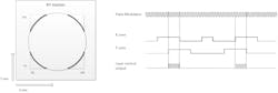
The next method to consider is distance-based pulse control, which is when the laser expects to see a trigger at a fixed distance along the path. The user defines the switch-on and switch-off positions, as before, but the firing signal is not continuously on. The controller may use this pulse to create a single shot from the laser or a combination of pulses for a particular laser processing recipe.
To improve application and process throughput, both pulse and PWM input can be controlled by advanced laser control capabilities from the laser firing controller. The different methods can also be combined to offer even greater flexibility, precision and throughput. The following sections show graphical examples of the different methods of control.
User-specified output pulse generation
The combination of high resolution, multiple axes and high speed within one system can be problematic for a user to calculate the distance along the outputting vector path. Fortunately, laser firing modules like the LCI can calculate the vector path for you. This makes it simple to define a fixed distance along the path, even when the path may be physically in one direction or a combination of multiple axes.
Firing at defined positions along a path—array-based or random firing
Rather than telling the system to fire at fixed discrete positions, it is also possible to define an array of positions where firing occurs. This can be used when an event may trigger a single shot or an alternative processing regime, for example, due to a material or process change—cutting vs. welding (Figure 13).
Isolating an area of interest—windowing

PWM mode
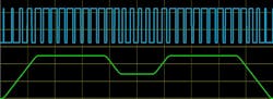
Figure 17 shows when windowing and PWM are combined to provide discrete areas of laser firing.
Summary
Fast and ultrashort laser sources open up opportunities for system integrators to incorporate these technologies into new applications. New tools offer the ability to process smaller features in a different way that was not previously possible.
However, for processes that require motion in the form of linear, rotary and nonlinear kinematics, it is essential that the laser firing is synchronized accurately with the motion path positioning. Electronics that allow this have been available in specialized motion controllers for some time, but industry is moving toward networks such as EtherCAT that make it simpler to add or link laser pulsing hardware. The significant advantages for the system integrators and builders of electrical cabinets brought by this level of connectivity allow them to choose the appropriate motion amplifiers and controls for the motion and the right interfacing for the laser.
Dr. Cliff Jolliffe is head of the automation market segment at Physik Instrumente (PI). Contact him at [email protected].
