How intrinsic safety aims to protect low-energy systems or signals from sensors, actuators and associated control signals for use in hazardous locations


The term "intrinsically safe" is often used in industries dealing with hazardous or classified locations. Although it is a very valid and safe type of protection for equipment used in these locations, the term is often incorrectly used to refer to equipment suitable for use in hazardous locations in general.
As there are many protection methods that can be used to protect electrical equipment for use in hazardous locations, it is important to understand exactly what intrinsic safety is in relation to a protection concept, what types of equipment typically make use of it and how to properly design and install equipment using intrinsic safety.
Intrinsic safety, like all other protection concepts, aims to reduce the risk of fire or explosion in a hazardous location. It is therefore important to understand how all protection concepts generally work toward risk reduction. For atmospheres that are hazardous due to the presence of gases or vapors, three key components are required for a risk to exist: an ignition source, an oxidizer and a fuel. These three elements are usually represented in a triangular relationship and referred to as the “fire triangle.”
If the triangle can be broken up or contained, the risks can be reduced to a tolerable level. In atmospheres that have a dust hazard, the explosion risk comprises two additional elements and is often represented as a fire pentagon. The additional elements are the suspension of the dust and the confinement of the dust.
Most protection concepts attempt to somehow eliminate or separate the relationship between these elements. When we talk about the intrinsic-safety method of protection, we are specifically targeting the ignition source portion of the relationship by limiting the amount of energy within a circuit to levels that are known to be appropriately low enough for the environment in which they operate.
By properly eliminating the ignition source, the required risk reduction is achieved and the added safety desired can be realized. Since intrinsic safety aims to limit the energy, only low-energy systems or low-energy signals can be considered. These primarily include sensors, actuators and the control signals associated with them.
There are two systems for classifying hazardous locations around the world: the class/division system, which is predominant in the United States and Mexico and still quite popular in Canada and other South American countries, and the zone system, which is recognized and used in all countries and regions.
One of the advantages of the intrinsic-safety type of protection is that it is possible to design equipment to cover all hazardous locations around the globe, for both gas/vapor and dust hazards, making it a very versatile method of protection.
When it comes to the design of equipment or installations that use intrinsically safe equipment, there are three specific terms that are used to describe the basic safety components. Understanding these terms is a first step in understanding an intrinsically safe system or installation as a whole.
The first is “intrinsically safe apparatus.” This is electrical equipment that is fully protected by intrinsic safety. Think of this as a field device, such as a sensor or transmitter of some sort. This can also be a stand-alone device such as a mobile device.
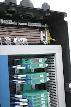
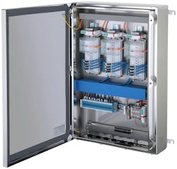
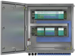
The second is the “associated apparatus.” This is equipment or a device that contains both intrinsically safe circuity and non-intrinsically safe circuitry. These are the devices that interface with the intrinsically safe apparatus to maintain the safety of the intrinsically safe apparatus. This can be thought of as a barrier or similar device that is designed to limit the energy to the field (Figure 1). There are many devices of this type that are designed for installation in a lower risk hazardous location, such as Div. 2 or Zone 2/22, but they can also be designed for installation in a non-hazardous location only, with their output signals going to the intrinsically safe apparatus in the hazardous location (Figure 2).
The third term is “intrinsically safe circuit.” This is an overall circuit that is not capable of being a source of ignition from either spark or thermal effect.
The criteria and the specific conditions for this assessment are described in the product safety standards that cover this protection concept. The main global standard detailing the design and testing of intrinsic safety is IEC 60079-11. In the United States and Canada, this IEC standard is adopted with some modifications known as national deviations. The national adoptions are UL 60079-11 for the United States and CSA 22.2 No 60079-11 for Canada.
To further explain this concept of protection, it is important to know that an apparatus must meet certain design criteria that take into account not only normal operation, but also failures within the product to ensure safety. There are many design elements within each device that need to meet the specific criteria of the standard to assure both electrical spark ignition safety and thermal ignition source safety.
An intrinsic safety evaluation within the apparatus can be very complicated and detailed, and often the devices contain additional circuitry for the sole purpose of providing needed protection for intrinsic safety. It is not sufficient for the device to only operate at low voltage and current. For example, sensors that comply with the NAMUR standard operate at very low voltages and currents, but this does not automatically make them intrinsically safe and suitable for use in a hazardous location.
When planning applications in hazardous locations, it is therefore important to understand the area classification in which the intrinsically safe apparatus is to be installed and to select one that is properly certified for use in this location. It is equally important to properly interface this intrinsically safe apparatus to a suitable associated apparatus to maintain safety. The associated apparatus must also be properly certified for use in an intrinsically safe circuit for the area classification of the end application.
Most equipment on the market, both intrinsically safe apparatus and associated apparatus, are certified with published intrinsically safe parameters, also known as entity parameters. These parameters allow the safe combination of an intrinsically safe apparatus and an associated apparatus to form the final intrinsically safe circuit.
In the United States and Canada, these details along with other relevant installation information are specified in a drawing known as the control drawing, and the marking on the device refers to this control drawing. The control drawing is required to be available prior to sale of the device so that an intrinsically safe circuit can be confirmed during the design phase.
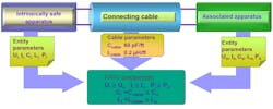
For the associated apparatus, the basic entity parameters are the maximum open circuit voltage, Uo (Voc), the maximum short circuit current, Io (Isc), the maximum power out, Po, the maximum capacitance that can be connected, Co (Ca), and the maximum inductance that can be connected, Lo (La).
For the intrinsically safe apparatus, the basic entity parameters are the maximum input voltage, Ui (Vmax), the maximum input current, Ii (Imax), the maximum input power, Pi, the maximum capacitance at the terminals, Ci, and the maximum inductance at the terminals, Li.
These entity parameters provide the designer with the building blocks to complete the evaluation and confirm that the completed circuit is an intrinsically safe circuit. The first set of comparisons are made with voltage, current and power. When the intrinsically safe apparatus was evaluated to IEC 60079-11 or a similar product safety standard, Ui (Vmax), Ii (Imax) and Pi were used as the maximum values allowed at the input terminals.
This forms the starting point for all further analysis within the intrinsically safe apparatus. As the safety analysis is based on these values not being exceeded, the connections from the associated apparatus to the intrinsically safe apparatus must also be limited based on criteria within IEC 60079-11 to ensure that the maximum values of the intrinsically safe apparatus are not exceeded (Figure 3). This is the basis of the entity parameters for the associated apparatus.
The analysis of the output of the associated apparatus has been carried out, and the published values Uo (Voc), Io (Isc) and Po have been determined as the maximum voltage, current and power that can be delivered by the associated apparatus.
So, if we confirm that Ui ≥ Uo, Ii ≥ Io, and Pi ≥ Po, we know that the associated apparatus cannot deliver more energy than the intrinsically safe apparatus is designed to handle and the safety of the intrinsically safe apparatus is maintained as far as these entity parameters are concerned. This leaves us with the question of the capacitance and inductance of the circuit.
The ability of a capacitance to quickly supply current and an inductor to quickly supply voltage affects the overall safety of an intrinsically safe circuit. These energy storage elements need to be limited to maintain the safety of the circuit. This is where Co, Lo, Ci and Li come into the assessment, but also the cable or the connecting wires. Yes, the wire is important. The connecting cable has a characteristic capacitance per unit length and a characteristic inductance per unit length.
For a given length of cable, the capacitance and inductance must therefore also be taken into account. These values are often referred to as Ccable or Cc and Lcable or Lc in control drawings. The datasheets for the cable likely refer to the capacitance and inductance as a nominal value per distance, with units in Farads per meter (F/m) or Farads per foot (F/ft) and Henries per meter (H/m) or Henries per foot (H/ft). If these values are not known, many control drawings give an indication of common values associated with typical single twisted-pair cables.
The evaluation that needs to be carried out to ensure safety for the capacitance and inductance is Co > (Ci + Ccable) and Lo > (Li + Lcable). This requires the total length of the cable from the associated apparatus to the intrinsically safe apparatus to be known so the total Ccable and Lcable can be determined.
If the exact distance is not known, err on the side of caution and choose a slightly longer cable length for evaluation. Alternately, since Co, Lo, Ci and Li are known, you can also determine the maximum cable length that would satisfy the relationship and then assure that the cable lengths for the installation do not exceed this distance. In either case there may be a catch to this simple assessment.
The control drawing of the associated apparatus may contain further information on the reduction of the Co and Lo values for situations where both Ci and Li are greater than 1% of the value of Co and Lo. This reduction factor is often referred to as the 50% rule. The details of this are beyond the scope of this article, but I mention it here only to bring it to the reader’s attention.
Once this evaluation has been made for a particular circuit loop, most installation sites require the components and calculations to be recorded in a descriptive system document, which will be used as a reference for initial signoff and subsequent audits and maintenance work to ensure the safety of the circuit and the entire installation.
To summarize, intrinsic safety is a specific type of protection and not a general term for equipment designed for use in a hazardous location. The basic principle of intrinsic safety is to limit energy in order to eliminate potential ignition sources. The energy available for the operation of an electrical or electronic piece of equipment is therefore limited.
In the United States and Canada, there is a required document in which the connection and installation requirements for intrinsically safe apparatus and associated apparatus are listed, known as a control drawing. The intrinsically safe circuit can be confirmed by correctly matching the entity parameters. A descriptive system document details all components, connections and calculations associated with each intrinsically safe circuit within the system for initial signoff and subsequent audits and maintenance.
Ryan Brownlee is hazardous areas SME at Pepperl+Fuchs. Contact him at [email protected].
