Closed-loop control of any device, parameter or process variable is one of the key concepts in manufacturing. Along those lines, any motion-control solution that involves position or velocity control of servo or dc motors, whether they are simple rotary spindles or those motors’ rotation is translated into linear motion in a gantry, will undoubtedly require position feedback to close the control loop for position and velocity.
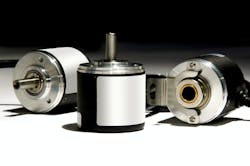
Encoders are the devices that provide this feedback to the motion-control system to facilitate the needed functions of controlling the motor behavior. Available in either optical or magnetic versions, an encoder is typically a rotating metal disk attached to or built into the motor itself and connected to the shaft.
The disk has many slots machined into it—so many, in fact, that they typically resemble spokes in a wheel. A light and light detector is mounted to the inside of the motor housing, and positioned so that the slots either allow light through the slot or it is blocked by the spokes of the encoder disk.
This generates a square wave output, with a frequency determined by the number of slots in the disk, and the velocity of the motor. Magnetic encoders work on a similar principle but replace the light and detector with a magnet.
In general, there are two main categories of encoders—incremental and absolute. But what are the differences, and how do you determine which is the right one for your application?
Incremental encoders are the simpler, smaller and less expensive of the two types, only registering a single train of pulses, with each representing an angular change of the motor shaft. This angular value is based on the number of holes in the encoder disk per revolution. With some simple math and pulse-counting in the motion controller, the motor can be commanded to a specific position or to a precise velocity.
If the rotary motor is connected to a linear slide via a gearbox or belt, each count of the motor encoder will represent a linear distance of motion of the gantry slide’s motion.
The incremental encoder is great at determining relative changes in angular or linear distance and velocity, but the only way to provide an absolute location is to register the axis with a home location via a proximity switch or digital input, which the motion controller or drive then keeps track of. From this position, relative moves are tracked and commanded.
This is where the main drawback of incremental encoders is exposed: If the system is rebooted or if a power loss occurs, this absolute position value is lost and the axis location is unknown until it is re-homed.
In a multi-axis gantry system, the homing routine may be a carefully orchestrated series of slow moves that carefully prevent things from crashing together while moving each of the axes to their respective home switch locations so that each axis is initialized and position commands can be given again.
Absolute encoders do not rely on a fixed home switch, because the encoder has numerous sets of slots in the disk and a detector for each set of slots. Instead of a simple train of square pulses, as with incremental encoders, the different sets of slots of an absolute encoder give a digital code or value for every granular position of the motor. Even after a power loss, the value only needs to be read directly for the controller to know the position of the motor.
For linear axes, multi-turn absolute encoders or linear encoders along the gantry slides provide this same functionality. This feature is key for systems where recovery from a loss of power would cause loss or damage to ware if the axes have to be homed to re-learn their absolute position, or if the production line cannot afford the time and loss of production to re-initialize the axes after a power loss.
Of course, there are tradeoffs with any technology, and the drawbacks of absolute encoders are their size, cost and complexity in motion-control programming. However, in the proper application, the feature of knowing absolute location on power-up is worth the perceived drawbacks.
Each of these technologies has its proper place in manufacturing, depending on the specific application and the boundary conditions of the process. Choose the encoder solution best suited for a specific need based primarily on whether the application can support a re-homing routine which will delay production and possibly require losing some of the ware that was in the machine at power loss. Secondarily, consider the cost and complexity of code to support an absolute encoder.
About the Author

Joey Stubbs
contributing editor
Joey Stubbs is a former Navy nuclear technician, holds a BSEE from the University of South Carolina, was a development engineer in the fiber optics industry and is the former head of the EtherCAT Technology group in North America.
