Figure 1 shows how area classifications are determined for North America using the class-and-division principle. The division is based on the likelihood of a specific type of gas being present at any point in time. As a rule of thumb, Division 2 assumes the potentially explosive gas is present one hour/year, and Division 0 assumes the gas is always present.
The second aspect of hazardous area control is the temperature rating. Figure 2 shows how the type of gas present determines the required "T-rating."


Simple apparatus are defined as those devices in the following three categories:
1. Passive components, including items such as switches, junction boxes, resistors and simple semiconductor devices that neither store nor generate energy. Sensors that use catalytic reaction or other electrochemical mechanisms are not normally simple apparatus.
2. Stored energy sources consisting of single components in simple circuits with well-defined parameters; for example, capacitors or inductors, whose energy storing values should be considered when determining the overall safety of the system.
3. Generated energy sources; that is, thermocouples and photocells that do not generate more than 1.5 V, 100 mA and 25 mW.
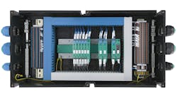
Comparison of Barrier and Isolator Schematics |
|
| Barriers | Isolators |
| Simple and reliable | More complex, statistically lower MTBF than barrier |
| Extremely accurate in many applications |
Active devices: power and heat Flexibility in bonding practice |
| High-integrity bond required Predictable response to earth faults |
Flexible response to earth faults |
| Inexpensive | Generally more expensive |
| Applications are defined in terms of voltage and resistance | Application-specific. Each barrier is defined in terms of the function that it is designed to perform. |
| Encapsulated design necessary Tight power supply limits (except ‘protected’/fused barriers |
Replaceable supply fuse common |
| Easier to fault find (earth reference) |
Wide power supply tolerance |
In addition to the above, the following (taken from the ISA standard) also applies to simple apparatus installations:
• Simple apparatus shall not achieve safety by the inclusion of voltage and/or current-limiting and/or suppression devices.
• Simple apparatus shall not contain any means of increasing the available voltage or current, for example dc-dc converters.
• Simple apparatus located in the explosive gas atmosphere shall be temperature-classified.
• Where simple apparatus forms part of an apparatus containing other electrical circuits, the whole shall be assessed according to the requirements of ISA–60079-11 (12.02.01)–2009.
Because with entity systems you need to understand interaction between each component on a loop, I/O card, barrier or field device, the entity concept works well for loops with one I/O card and one field device. However, if you have multiple devices on a wire pair, as with fieldbus systems, the number of combinations that need to be verified quickly grows exponentially. This is one of the reasons most process fieldbus systems use FISCO as described in the June 2010 issue of Control.

• All terminals for intrinsically safe circuits shall be separated from terminals for non-intrinsically safe circuits where intrinsic safety can be impaired by external wiring that, if disconnected from the terminal, can come into contact with conductors or components by distance or terminal location.
• When separation is accomplished by distance, the clearance between bare conducting parts of terminals shall be at least 50 mm, including ensuring that contact between circuits is unlikely if a wire becomes dislodged.
• When separation is accomplished by locating terminals for intrinsically safe and non-intrinsically safe circuits in separate enclosures, or by use of either an insulating partition or an earthed metal partition between terminals with a common cover, the following applies:
• Partitions used to separate terminals shall extend to within 1.5 mm of the enclosure walls or, alternatively, shall provide a minimum distance of 50 mm between the bare conducting parts of terminals when measured in any direction around the partition.
• Metal partitions shall be earthed/grounded and shall have sufficient strength and rigidity to ensure that they are not likely to be damaged during field wiring.
The final critical element in any IS circuit is the important issue of what to do with any "extra"energy that might result in the event of a fault in the loop, such as a short circuit.

The function of the IS ground is to provide a secure, high-integrity, low-impedance path through which fault currents will flow, while minimizing voltages seen in the hazardous area. The most likely source of high-voltage invasion is from the local distribution transformer feeding the control system and, practically speaking, the IS ground is there to shunt fault current from such an invasion back to the neutral of this transformer. It, therefore, has to be of low impedance to be the preferred path for the fault current (while the barrier fuse blows).
Why Use IS?
Now that we know the basics of the various components of an IS circuit and the associated restrictions regarding its installation, what are some of the arguments for using intrinsic safety that explain why it is so widely used in other parts of the world?
• Cost — IS systems do not require lockable fused isolators, protected cable, special glands or explosion-proof enclosures. These not only lead to higher initial costs, but also require additional time whenever the junction box or the device needs to be opened or closed.
• Use of unarmored cable — The system is electrically, not mechanically, protected, though mechanical protection might be desired for other reasons, such as crush resistance.
• Fault-tolerance — IS is the only technique that remains safe after faults develop in cables and fallible components.
• Live maintenance — IS is the only technique that permits live working without gas clearance certificates for all area classifications.
• Personnel safety — Extra-low voltages and currents mean there is minimal risk of injury in the event of contact with bare wires.
IS "works" by reducing the power going to the field. The simpler alternative, which uses diodes/resistors, is called a passive zener barrier. If a barrier introduces too much voltage drop due to too high a resistance being added to the network by the barrier, resulting in insufficient power to drive the output full scale, then you might need to use an isolator. Since isolators are separately powered, they do not present as large a load to the loop.
This happens on occasion for analog-output devices such as valves. The figure and table on the previous page show the differences between these two alternatives.
Is intrinsic safety part of your future? Only you can decide. However, as you can see, there are a number of reasons that you should consider it when designing a new installation. With our increasing focus on safety, IS installations reduce the overall risk of explosion through human error.