Are purged enclosures and intrinsically safe barriers necessary?

A Control Design reader writes: Our facility processes propellants and explosives with many areas classified as hazardous—Class II, Div. 1. Normally, we install the controller and I/O in a suitably purged enclosure and use intrinsically safe barriers for most field device connections. I'm not sure this is the best solution on a large canister-filling project, where there are nearly 500 I/O points on the hazardous-area automation. Because of the large installation and space limitations in the hazardous area, the main control panel will need to be located outside the hazardous area. How do I keep from running more than 500 wires, about 70 ft each, between hazardous and nonhazardous areas? What are my options?
ANSWERS
Reduce wire runs
This method—running a cable from each I/O point in the control cabinet through intrinsically safe barriers to the sensor or other device in the hazardous area—is certainly the way engineers have dealt with intrinsic safety for years. Fortunately, there are new options to reduce the number of lengthy wire runs, which can be very cost-intensive in terms of expense and installation effort. New methods and technologies could reduce the effort down to one cable rather than 500 in some instances.
First, consider reducing the number of cables and the size of the control cabinet by locating intrinsically safe components in the production area. Intrinsically safe I/O terminals can be installed in Zone 2/22 and connect with intrinsically safe sensors and actuators in Zone 0/20 (Figure 1). In process environments, IP20-rated I/O terminals can be mounted on DIN rail in separate enclosures. A single cable can connect each segment of intrinsically safe I/O terminals to the controller, reducing the required cables and intrinsically safe barriers.
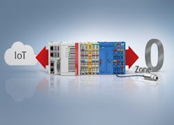
Figure 1: Terminals rated for Zone 2/22 bridge the gap between intrinsically safe sensors and actuators in Zone 0/20 and cloud-connected controllers.
Second, explore the benefits of pluggable, circuit board-mounted I/O modules (Figure 2). These can be placed in Zone 1/21 when located inside an explosion-proof Ex d housing. As a result, only one Ethernet cable would need to run from the control panel to the I/O enclosure, allowing much shorter cable runs from the I/O to the sensors without requiring multiple barriers. Because this requires the design of a custom circuit board to plug the I/O terminals into, it might not be the best solution for a one-off project. However, it is an excellent option when completing multiple machine/equipment builds or installations in this facility or others.
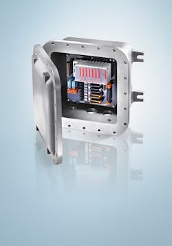
Figure 2: Space-saving, pluggable terminals can be used in Zone 1/21 when located inside explosion-proof Ex d enclosures.
The EtherCAT industrial Ethernet protocol provides benefits for both of these solutions. Because EtherCAT can support more than 65,000 devices on one network with real-time performance, the relatively small number of sensors in this instance will not cause problems. In addition, EtherCAT is an inherently open solution, easily integrating with multiple fieldbus and network protocols, such as HART, Profibus, DeviceNet, CANopen or EtherNet/IP. Once data from all these protocols are gathered from all connected sources, they can be transmitted over a single Ethernet cable once it reaches an EtherCAT I/O segment. This should eliminate the bulk of long cable runs into the Class II, Div. 1 environment without requiring changes in the existing machine controller or network architecture.
SREE POTLURI / I/O product specialist / Beckhoff Automation
Two options

Because the reader believes he or she is unable to install any remote I/O, due to space constraints in the hazardous area, the best solution at this point is using junction boxes to consolidate the intrinsically safe (IS) wiring in the hazardous area back to the PLC in the unclassified area. Two options are described below.
Option 1: I/O possibilities
If there is some space to install remote I/O, then Type X pressurization enclosure—although generally done with Class I rather than Class II, it makes Div. 1 areas essentially non-hazardous—is certainly an option (Figure 3). The reader could put the PLC with IS barriers in the Type X pressurized enclosure, or I/O in the Type X pressurized enclosure and run Profibus DP back to the PLC. Then put IS process wiring receptacles, or IS glands, on the Type X pressurized enclosure because they carry FM approval for intrinsically safe, and by definition IS wiring only requires Div. 2 seals.
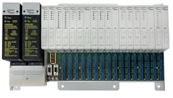
Figure 3: If there is some space to install remote I/O, then Type X pressurization enclosure—although generally done with Class I rather than Class II, it makes Div. 1 areas essentially non-hazardous—is certainly an option.
Under NFPA 496 Standard for Purged and Pressurized Enclosures for Electrical Equipment, 2008 Ed., Section 4.2.3, all Div. 1 seals not part of the pressurized system need to be explosion-proof, although I would make the case for IS wiring since by definition it is energy limited and our EX receptacles do not allow the mitigation of gas, and, as dust particles are larger than gas, they would never pass dust either.
Our largest backplane I/O system from allows for 192 intrinsically safe I/O discrete connections or 96 analog connections, which would mean, for 500 I/O, the reader would need at a minimum three racks. In addition to the racks, the reader would need to purchase all the I/O cards but would not have to buy IS barriers and install them in the pressurized enclosure, so is saving money and space.
Again, three or more racks may or may not be possible depending on the space constraints of the hazardous area. Our I/O system comes with a redundant Profibus DP communication card that will allow for both a smaller footprint in the hazardous area by not requiring IS barriers, and it’s possible to consolidate the 500 cables down to two, approximately a 99% reduction in cabling from the PLC in the unclassified area to the hazardous area.
Option 2: Junction boxes with homerun cables
If there is no space in the hazardous area for multiple I/O system racks, then, to reduce the amount of cables from the hazardous to unclassified area, the reader would simply install the PLC with IS barriers in the nonhazardous area, then install process wiring junction boxes in the hazardous area and then run homerun cables back to the unclassified area.
With eight-port junction boxes, it’s possible to consolidate the 500 cables down to 63 cables, approximately an 87% reduction in cabling. The only drawback is the reader would have to purchase field wireables or overmolded cables for all the junction boxes and/or field devices.
JOHN VU / product engineer for interfaces, fieldbus technology division / Turck
Make the connection

One thing to consider before you abandon the idea of 500 I/O points worth of intrinsically safe (IS) wiring is the advantages of running IS connections into the hazardous area. It greatly eases the wiring since there are several wiring and cabling methods permitted for IS connections into a Class II, Div. 1 area. Without IS, any wiring you take into the hazardous area will be limited. As you likely know, this usually means threaded metal conduit, metal-clad cable or similar types of approved wiring methods for non-IS signals in Class II, Div. 1.
In keeping with the all-IS approach, you may be able to reduce the number of wires that need to be run for your installation and still maintain IS for all of your signals. There are IS barriers that support connecting to two-contact switch type or NAMUR type sensors over a single pair of wires, cutting the needed wire run back to the safe area in half. This method does come with some switching-speed limitations but can be an option to reduce wire count.
A second method that could be considered to maintain all IS signals but reduce the number of wires is to power several 4-20 mA devices with a single IS barrier and run them in complete digital mode via HART signals. There would be some obvious limitations on the number of devices and what could be done with this method, but it is an option to consider.
Another option to reduce the wire count from the safe area to the hazardous area would be to use a bus system like fieldbus or Profibus to communicate to a number of hubs, each hub having a number of spurs or I/O connection points. Each hub used to distribute I/O around the hazardous area could have IS connections out to IS devices for the I/O point data, easing this part of the wiring install. So the advantage is a reduced number of wires that would need to be run a long distance, and the connections to each I/O point would be IS. The disadvantage is that it introduces the Class II, Div. 1 installation and wiring methods for hubs and for the bus cabling.
Depending on the nature of the I/O data, a wireless network for some number of the data points could be deployed, and direct IS wiring for the rest of the points could be done. WirelessHART or other wireless protocols can be used in hazardous areas to allow for communication back to a control system. This could eliminate some the IS wiring that would be needed and also limit the amount of Class II, Div. 1 wiring that would be needed. There may still be a need to deal with power to the devices, so some sort of power bus installation may still be needed to Class II, Div. 1 requirements, or batteries to power the device and the radio attached, but the overall number of wires would be reduced.
Finally, you could also consider breaking up the single large control cabinet. If there is room, a few smaller control cabinets could be in the hazardous area with protection by pressurization, and IS I/O from the pressurized enclosures could be used. This might have been passed over based on the assumption that a pressurization control system would be needed at each enclosure. However, this would not necessarily be required. There are methods to connect a number of enclosures together and treat them as a single enclosure, as far as pressurization monitoring and control is concerned. There are also pressurization control systems that can monitor two separate enclosures at the same time. So, it may be possible to have two or four smaller enclosures placed around the hazardous area controlling your process and have them connected such that a single pressurization control system could monitor them all.
RYAN BROWNLEE / compliance and technology consultant, product management team / Pepperl+Fuchs
Remote I/O
A wireless approach would seem to be the best possible solution approach, but an additional option could be to use remote I/O. You would collect the data in the XP area into the remote I/O hardware. Transmit it via fiberoptic, if necessary, or cable to the safe area where a PLC can process the data. This would eliminate the 35,000 feet of cabling.
TED COWIE / vice president, sales, safety and industrial products / Motion Industries
Distribute the I/O
One option is an intrinsically safe distributed I/O platform. One of the benefits of a distributed I/O solution is that it allows mounting of I/O away from the main control panel and nearer to field devices and instruments. The I/O modules should carry a Zone 2/Class I, Div. 2 approval and be suitable for Zone 2/Class I, Div. 2 gas hazardous area mounting in an appropriate enclosure. For dust hazardous area mounting (Zone 22/Class II, Div. 2), do note that additional special cabinet specifications must be met. As intrinsically safe applications vary by the required level of safety and security aspects, I recommend discussing your system layout and architecture with your vendor.
ZIN MAY THANT / senior product specialist / Rockwell Automation
What is nonhazardous?
To be a bit clearer on what is meant by nonhazardous area, I’ll add in the reference to a Div. 2 area. To me, nonhazardous means safe area, but I’ve heard people refer to a Div. 2 area as nonhazardous.
I am not aware of any wiring reducing options for runs from the Div. 1 area to the Div. 2 area. If looking to reduce the length of the wiring runs from the Div. 1 area to the safe area, then there are options by ending your wiring runs in the Div 2 area. The two options I can think of are using remote intrinsic safety I/O or using an intrinsic safety fieldbus system. With both of these technologies, there are manufacturers that make Div. 2-approved devices that offer network cabling interfaces to take your data to the safe area. My first choice would be the remote intrinsic safety I/O because it’s the most flexible system when it comes to input and output options.
DEREK SACKETT / senior product marketing specialist for interface analog and enterface Ex / Phoenix Contact USA
One cable
First of all, I myself am not an expert in hazardous locations. With that, I do represent some product that can be placed in Class 1 Div 2 locations. Have you looked into remote I/O options? You will still need to place the remote I/O block in safe areas, but, instead of running the 500 wires 70 ft, you will be able to run a single network cable such as EtherCAT the 70ft and then break out your 500 I/O points from the remote I/O block.
CLARK KROMENAKER / product manager—HMI, IPC, controllers, I/O, software / Omron
ALSO READ: When machines need intrinsic safety

Mike Bacidore is the editor in chief for Control Design magazine. He is an award-winning columnist, earning a Gold Regional Award and a Silver National Award from the American Society of Business Publication Editors. Email him at [email protected].
Control Design Newsletters
About the Author

Mike Bacidore
Editor in Chief
Mike Bacidore is chief editor of Control Design and has been an integral part of the Endeavor Business Media editorial team since 2007. Previously, he was editorial director at Hughes Communications and a portfolio manager of the human resources and labor law areas at Wolters Kluwer. Bacidore holds a BA from the University of Illinois and an MBA from Lake Forest Graduate School of Management. He is an award-winning columnist, earning multiple regional and national awards from the American Society of Business Publication Editors. He may be reached at [email protected]
