Machine-vision technology has grown, large and small, to touch most industrial automation applications. Trimmed-down, cost-effective options are servicing small operations with simple applications, while larger systems, harnessing massive processing power, are operating inspections for the largest production lines under sensitive and demanding conditions. Three manufacturers—Teledyne Dalsa, BitFlow, Beckhoff Automation—offer unique innovations. For three more machine vision building blocks, read "Another look at vision systems."
Multifield imaging technology
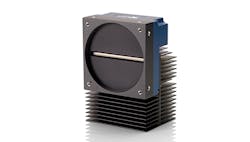
For machine-vision applications that demand high sensitivity in light-starved conditions, camera speed and capability is paramount. Teledyne Dalsa has been selling its time delay integration (TDI) cameras for many years, and its latest design, the Linea 16K multifield camera, uses new technology to make image capture even faster in the lowest light environments.
“A lot of high-performance inspections require different lighting configurations,” says Xing-Fei He, Ph.D., senior product manager, Teledyne Dalsa.
The lighting configuration for an application focuses on different fields, or angles of light incidence. “When you want to detect a defect, you need to adjust the lighting angles,” says He. “The lighting angles play an important role to enhance the contrast between the defect and the background.”
For brightfield conditions, the light is shining on the object, lighting the object and reflecting back to the camera. Darkfield uses a very wide angle to light the object but not reflect back to the camera. Backlight is illuminating the object from behind or underneath, which is often used for the inspection of transparent objects, He says.
Current imaging technology requires three separate scans—with brightfield, darkfield and backlit lighting—and then combines the scans together. Teledyne’s multifield imaging technology, takes those three scans together. “Multifield significantly improves tact time and detectability,” He says. The technology uses light sources at different wavelengths, which are captured simultaneously by the multi-array TDI sensor with wafer-level coated dichroic filters that separate the images.
“It’s different than the color imaging that we’ve been using for a long time because in color imaging there’s a lot of overlap on the spectrum,” He says. This causes spectral crosstalk between RGB channels or distortion of the images. The multifield technology minimizes spectral crosstalk, as its sensor has three different arrays to capture three different wavelengths. “You can shine a light on the brightfield with a red wavelength, and darkfield is green, and backlight is the blue wavelength that all shine onto the same point at the same time; and you can capture three images in a single scan,” He says.
The charge-domain CMOS TDI camera also improves on noise levels, compared to a more traditional CCD TDI technology (Figure 1). TDI technology uses two different methods—digital domain or charge-domain—to capture multiple rows in the same spot of a moving object and then sum them all together; and the summing process has noise associated with it.
To achieve high sensitivity, He says, you need a charge-domain device, whereas digital domain can support a small number of rows. With charge-domain TDI, the camera can sum more rows and do it more quietly.
The speed of the camera can improve on tact time, or total assessable cycle time, and detectability in an automated optical inspection (AOI) system. “Tact time is the number one spec in any inline equipment in the production line to make a return on investment, and that’s related to the speed of the camera,” He says.
The multifield camera is ideal for applications, such as flat panel display (FPD) inspection, PCB inspection, wafer inspection and medicine. Many of those applications require high magnification. FPD and PCB inspections often require resolution in the sub-microns. With the introduction of 5G networks, He says, circuitry design is only getting denser, requiring inspections to capture more detail.
Wafers are used in the manufacture of integrated-circuit (IC) chips, and their inspection requires resolution at the nanometer scale.
Also read: How machine vision systems and robots have influenced each other
The Teledyne TDI camera has also been designed for DNA sequencing. “That’s becoming very popular because of the pandemic right now, and we need to detect DNA,” He says. The scale is similar to wafer inspection; the magnification is very high. “The camera needs to detect and process huge amounts of data,” He says.
“The most important features about the camera are the capability and the speed,” He says. “The high resolution and throughput of the camera not only improves detectability, but the camera can also align images automatically and that saves a lot of time in the process.”
No interruptions
For inspection applications that require the highest processing speeds and highest resolution images, a frame grabber can serve as another solution. A frame grabber is an industrial video card used to transfer images from a camera into a computer. BitFlow makes the Claxon-CXP4, which is a quad CXP 12 PCle Gen 3 frame grabber. It accelerates video transmission speed to 12.5 Gb/s per camera in a four-camera system. This latest faster version was launched in June 2020 and is twice as fast as the CXP 1.1 standard.
“CXP 1.1 interface speed was at 6.25 Gb/s per link, and the standard high-speed camera has four links, so that gives you a total of 25 Gb/s, which is about 2.5 GB/s of data,” says Donal Waide, director of sales for BitFlow. “This new standard is CXP 2.0, and one of the highlights of CXP 2.0 is that the speed is doubled to 12 Gb/s, again aggregated over four links, it’s approximately 5 GB/s of data for the camera.” The frame grabber is ideal with a multiple camera solution—four single-link cameras, two dual-link cameras or one dual-link and two single-link cameras.
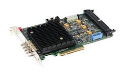
Figure 2: The frame grabber achieves virtually zero latency (in the nanosecond range) and exact synchronization between all the camera images because it doesn’t use CPU cycles.
“While these systems have been a fixture in machine vision for decades, what is new is the use of CoaXPress. It allows multiple cameras to be linked by a single frame grabber over long, inexpensive and very robust coaxial cables,” Waide says. The frame grabber achieves virtually zero latency (in the nanosecond range) and exact synchronization between all the camera images because it doesn’t use CPU cycles (Figure 2). “So typically, when the CPU is used, the CPU can be performing a number of different tasks in the computer, whether it’s moving data around or doing some processing, and what happens is the CPU is not always available, so therefore, you get interrupts,” Waide says. “Because the frame grabber is not using any CPU, there’s no interrupts.” With the multiple cameras all running to the same frame grabber, images can be synchronized.
As an example, this technology could be used to inspect cell phone screens. “We’ve all dropped our phones, and, say, the 15th time you drop your phone, it cracks,” Waide says. Anyone that buys a phone can look at it, and, with the naked eye, they’re not able to see any defects that would lead to issues. “But, because of the higher-resolution sensors in the camera, you can examine right down to the micromillimeter, and you can actually see where the potential issues might be happening, and this is why you can drop that phone 14 times without an issue,” Waide says.
Faster cameras and faster processing can also lead to drops in the overall cost of production for a manufacturer. What used to take six cameras, Waide says, can now be done with one, plus inspection speeds are getting quicker. “Because the manufacturer now has to buy one camera instead of six and has to buy fewer processing cards or less memory, the cost of manufacturing drops,” Waide says.
The BitFlow frame grabber is applicable only for the top 5% of applications, in terms of their need for processing speed, Waide says, making BitFlow a boutique company for the “Cadillacs of the industry,” he says. Machine designers who are unsatisfied with the limitations of other machine-vision standards, such as Camera Link, Firewire, USB3 and GigE Vision, will find an increase in speed from CXP, says Waide.
“The required precise synchronizing of cameras in a multi-camera configuration is a byproduct of a deterministic interface,” Waide says. CXP and Camera Link are inherently deterministic. GigE Vision and USB3 are not. Ultimately, this makes CXP “perfectly predictable,” Waide says. “With the grabber we can calculate to a very high accuracy what the latency would be in these systems. Without a frame grabber, you are at the mercy of the CPU and the number of interrupts it's handling at any given time,“ he says. Additionally, Waide says this request often comes from potential customers as they are trying to calculate the setup of their encoder triggers to match the image capture sequence.
Controls integration
Though vision systems have become more cost-effective in the past decade, cost is still often a consideration for machine builders. Many options exist, so users can find the exact system that fits the specific application. “Now it’s become very common that most machines have some sort of machine vision on them,” says Daymon Thompson, TwinCAT product manager at Beckhoff Automation.
Traditionally, the market has supported three types of systems, Thompson says. The stand-alone camera is known as a smart camera. They can be expensive, and, in a multiple camera setup, “the economy of scale just doesn’t work,” Thompson says. While it can work, it can be very expensive.
PC-based vision systems run on the operating system. “It, therefore, has the power of the PC, but the timing is beholden on the operating system,” Thompson says.
The third method, he says, is a hybrid—the stand-alone vision controller with a separate camera.
Beckhoff has introduced another option by integrating machine vision and image processing into the machine controls. “In our approach, we’ve always been PC-based, with a real-time environment, so not beholden to the timing of the operating system, so that made a really great platform to bring in vision algorithms,” Thompson says. “We built a vision driver to be able to connect to the GigiE vision cameras, and we bring the image directly into the machine controller.”
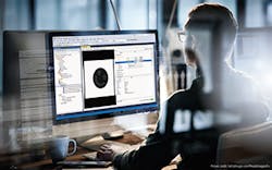
Figure 3: Software allows users to implement watchdogs to monitor the timing of image-processing functions.
With stand-alone vision systems, they process the algorithms and then need to send the results to the machine controller, and then the machine controller cycles and processes those and makes a decision based on the result. “And there’s latency that happens there,” Thompson says. High-speed vision applications, where product is coming by very quickly or guided with motion, can be challenging, if latency occurs.
“We brought vision into the familiar programming environment,” Thompson says. “Because it’s on a PC, we can leverage the multi-core capability of PCs.” This allows users to split the motion controls and vision processing onto different cores, all isolated from the operating system. “Basically, it means a wide choice of cameras, extremely fast processing of the image and very closely coupled with the machine controller,” Thompson says. Also, controls engineers can design their own vision applications with familiar languages.
TwinCAT Vision is ideal for any industrial image-processing application, such as quality inspection and track-and-trace. The system also stores images in the PLC memory for easy access. “Anywhere you have to do a fast reaction on the results of the vision algorithm, so, for example, a bottling line where you’re doing several hundred or thousand per minute and looking to see if the cap is completely seated, or the label is fully on the bottle,” Thompson says, “the faster you can react to the results, the faster you can pull that bad product off the line.”
The software also allows users to implement watchdogs to monitor the timing of image-processing functions (Figure 3). In a continuous flow operation, any anomaly can slow down the process. Instead, the watchdog function can note that there was some kind of anomaly without slowing production. “Traditional solutions would process the entire image before it would give you results back, but, by that time, the inspection could have missed several other products,” Thompson says.
The system is also suited for anything coupled with motion. “We can actually close position loop on an axis with feedback from the camera, which is pretty unheard of in the industry because of the latency that’s there,” Thompson says.
The system was also designed for easy image retrieval. A stand-alone camera setup can make it challenging to get the current image into the HMI. “A lot of times that involves having the image being stored to an intermediary file, like on a PC, and then displayed on the HMI,” Thompson says. “So that was one of our goals for this design, making it very easy to show the current image, the last image, even be able to manipulate the image a little bit by adding text to it,” Thompson says. “But it takes a controls engineer a couple minutes to add the camera image to the HMI. It’s very simple, really cleanly integrated.”
The TwinCAT Vision technology can be more affordable, compared to stand-alone camera and controller systems. “The reason is the underlying infrastructure is really already in place,” Thompson says. Using the machine controller and the controller that’s already there to program the vision side requires using one of the network cards to hook up a camera and adding software functions to do the processing. “We can add a camera to an existing controller for less than it would be ad a stand-alone camera,” Thompson says. “The savings really come from a multi-camera situation.”

About the Author

Anna Townshend
Managing Editor
Anna Townshend has been a writer and journalist for 20 years. Previously, she was the editor of Marina Dock Age and International Dredging Review, until she joined Endeavor Business Media in June 2020. She is the managing editor of Control Design and Plant Services.
